


Caution
11
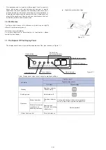
6. Air Duct Installation
6.1 Piping Design and Installation
Figure 6.1
Note: On-site preparation required for all components except for the air conditioner.
For Inspection
Canvas Joint
Canvas Joint
Air outlet
Heat insulation layer
Heat insulation layer
Return
Air Inlet
•
Once the air conditioner body and the canvas joints are riveted together, the upper flange plate must be secured with screws.
(M6 x 12 screws are prepared on site.)
(1) In order to prevent short-circuit air delivery, the piping for air outlet and air return ducts must not be too close.
(2) The indoor unit does not have an air filter installed. The air filter must be installed at a location like an air inlet where it can be easily maintained.
(Without an air filter, dust particles may stick to the air heat exchanger which will make the air conditioner prone to failures and water leakage.)
(3) Before installing the air duct, ensure that the static pressure of the air duct is within the permitted range of the indoor unit (see section 6.2).
(4) Connect the canvas duct to the air return and air outlet ducts to prevent vibrations from the indoor unit transferring to the ceiling.
(5) Use heat insulation materials at a thickness of 25 mm or more to prevent condensation on the air duct.
(6) Connect the air duct as shown in Figure 6.1.
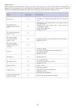
6.2 Fan Performance
7.1/8.0kW
200Pa
190Pa
180Pa
170Pa
160Pa
150Pa
140Pa
130Pa
120Pa
110Pa
100Pa(default)
90Pa
80Pa
70Pa
60Pa
50Pa
30Pa
0
20
40
60
80
100
120
140
160
180
200
0
5
3
1
0
0
3
1
0
5
2
1
0
0
2
1
0
5
1
1
St
a
ti
c
p
re
ssu
re
(P
a)
Air
flo
w (m
3
/h)
9.0kW
200Pa
190Pa
180Pa
170Pa
160Pa
150Pa
140Pa
130Pa
120Pa
110Pa
100Pa(default)
90Pa
80Pa
70Pa
60Pa
50Pa
30Pa
0
20
40
60
80
100
120
140
160
180
200
1130
1180
1230
1280
1330
1380
1430
St
a
tic
pr
ess
ur
e
(P
a)
Air
flo
w (m
3
/h)
Содержание Gama CND
Страница 2: ......