E T X S E R I E S L I T H I U M B A T T E R I E S
3
In the event of a charging system failure where the voltage increases to above 15.2V, the
resistance to charging current increases, and above 16V the charging current is completely
blocked. This design offers charge voltage protection up to 40V, exceeding the requirements of
RTCA’s performance specification DO-311. The discharge current (current out of battery) is
unaffected in this situation.
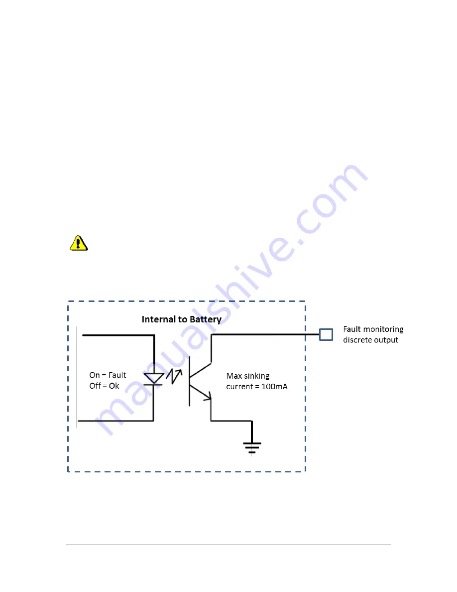
The battery’s micro-controller monitors all failure modes, and reports failures with a built-in
LED indicator and discrete output. The discrete output for external fault monitoring is a
single wire connection with ¼” quick connect terminal. The output is a “current sinking”
type circuit (see diagram below) that can handle 100mA (connects the discrete output to
battery ground if a fault is present). This output can be connected to an external 12V LED
or general purpose discrete input of an EFSI. The fault output has two states; flashing (5
second cycle time) or solid. The flashing fault can indicate that the battery needs to be
charged (check voltage of the battery and if less than 13.3V, you need to charge it) or it can
indicates an abnormal condition with the batteries lithium cells such as one or more cells are
over-discharged (>80% depth of discharge) or over-charged or cell voltage imbalance. The
solid fault indicates a BMS hardware failure. For example, if the micro-controller fails the
fault indication output is activated (on solid).
A sustained fault can indicate a serious issue with the battery or vehicle charging system that
requires immediate attention. Discontinue use until the issue is resolved and the battery no longer
indicates a fault.
Continued use of a faulty battery can result in a cell rupture, the release of
flammable vapors, smoke and or a fire.


