


2
ASSEMBLING & DISASSEMBLING THE TOURING PIANOMIC
™
The PianoMic
™
System is quick and easy to install. Once you have initially set up
the PianoMic
™
System you will be able to do it from that point on in just a few
minutes. Here are some helpful guidelines:
CAUTION – the microphone heads and goosenecks are permanently at-
tached to the two PianoMic
™
telescoping tubes and cannot be moved, or re-
moved. Once assembled, the distance between the two goosenecks is fixed
at 16 inches (one-third of the width of a piano keyboard).
Check that all items are included with your Touring PianoMic
™
System by using
the list of “Items Enclosed” on page one of this manual.
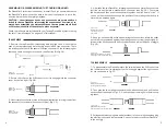
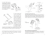
TO ASSEMBLE
1. Remove the two PianoMic
™
telescoping bars from the case. Notice that on
each of the two telescoping bars, there is a special XLR type connector. There
is a rotating collar next to the special XLR type connector on the telescoping bar
that has a cable coming out of one end, (see Section B in Fig 1-A).
Figure 1-A
Sections A & B of PianoMic
2. Rotate the collar on the XLR connector so it is snug against the connector
cover, but not too tight. (Fig. 1-B)
Figure 1-B
Rotate collar all the way
to the right.
3. Next, rotate the collar two turns in the opposite direction (moving it away from
the connector cover toward the connector pins). (Fig. 1-C)
Figure 1-C
Rotate collar two
turns to the left
3
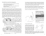
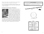
4. Now, take the two PianoMic
™
telescoping sections and mate the connectors
just like you would mate a standard XLR connector (see Fig. 1-D). First mate
the keyways and then push the connectors together until you hear a “click.” If
you do not hear a click, then change the position of the rotating collar and try to
mate the two sections again.
Figure 1-D
Mate the two sections
by pushing until you
hear a click.
5. Once you have heard the click when mating the two sections, rotate the collar
until it is firmly positioned against the mating connector cover (finger tight). At
this point two sections should be firmly attached and will not be loose or wiggle.
(Fig. 1-E)
Figure 1-E
Rotate collar all the way to the left
firmly against the left connector body
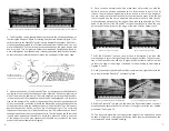
TO DISASSEMBLE
7. To disassemble the PianoMic, rotate the collar between the XLR connectors
the full distance from its mating half until it is snuggly against the right connec-
tor body as shown in Fig. 1-F.
Figure 1-F
Rotate collar all the way
to the right connector body
8. Then grab the two mating connectors (one with each hand) and pull the two
sections apart as shown in Fig. 1-G.
Do not pull apart holding onto the telescop-
ing tubes.
Figure 1-G
Separate the two sections
by holding onto each connector body
9. Collapse the telescoping bars and place them in the carrying case along with
the electronics box and leather pouch. Now you’re ready to take your PianoMic
™
to the next gig.
Содержание PM40T
Страница 8: ...Notes 12...


