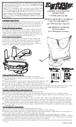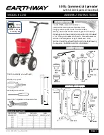


13.
Install handle shaft to lower handles
and pivot & bracket assembly as shown.
Using 1/4-20 x 1-3/4” bolts and lock-
nuts.
T
IGHTEN
BOLTS
AND
NUTS
NOW
.
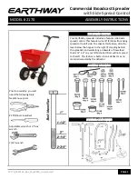
14.
Install (1) 1/4-20 regular nut
(
NOT
A
LOCKNUT
)
on to control rod as shown.
Next install the two 1/4-20 x1” Stainless Steel bolts into holes locates on each
side of the hopper and secure with 1/4-20 lock nuts. Next slide Debris Screen
under the two bolts inside the hopper.
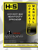
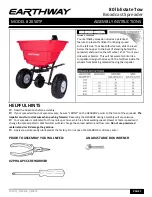
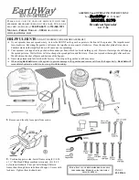
15.
Install flattened end of control rod in to lever on
gauge as shown. Turn to lock in place. Next push lever
forward to setting
“0”.
Align control rod with hole in
pivot bracket, pull lever backward to insert control rod
through hole in pivot bracket. Now install 1/4-20
regular nut on to control rod.
DO NOT TIGHTEN NUTS YET.
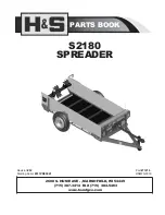
16.
Pull lever back to setting
“30”
as shown. Next push pivot &
bracket forward so that the shut off plate in the hopper is in the full
open position.
REMEMBER SETTING “30” ON THE FLOW
CONTROL LEVER MUST PLACE THE SHUT-OFF PLATE
IN THE FULL OPEN POSITION TO BE PROPERLY CALI-
BRATED.
Now tighten the nuts against the pivot bracket to pre-
vent change in calibration.
17.
Insert agitator to pinion shaft on inside of hopper.
Note:
Position of flat side of agitator. This pin should be installed as
shown.
PAGE 4