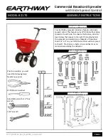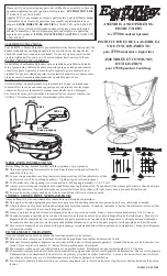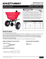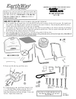


7.
Slide axle bushing over axle and into axle
bearing to both sides as shown.
8.
Install drive wheel to axle using pin hole nearest to lower handles as shown. Insert 2”
cotter pin through wheel and through axle. Bend with pliers to prevent pin from falling
out.
10.
NOTE: BEFORE INSTALLING GAUGE AND UPPER
HANDLES TO HANDLE SHAFT, UPPER HANDLES FEATURE
THREE POSITIONS FOR OPERATOR’S COMFORT.
If opera-
tor chooses middle or upper positions, use handle spacer in hole
nearest to handle grips. Insert 1¾” bolt through upper handle
,
then through handle spacer through other upper
handle. DO NOT
TIGHTEN LOCKNUT YET. TIGHTEN THIS NUT LAST.
Install
gauge & lever using (2) 1¾” bolts. Be sure gauge is on left hand
side. Tighten locknuts to gauge first. TIGHTEN NOW.
11.
Insert pivot rod into shut off plate as shown. Turn to lock in
place.
[ N
OTE
: E
XTRA
BEND
IN
ROD
END
ATTACHES
TO
THE
SHUT
-
OFF
PLATE
.]
12.
Insert other end of pivot rod into pivot and bracket
assembly
as shown. Turn to lock in place.
PAGE 3
9.
Install coast wheel to axle using outside pin hole. As shown, insert 1” cotter pin
through axle
(
NOT
THRU
THE
WHEEL
)
. Bend with pliers to prevent pin from fal-
ling out.
TURN SPREADER UPRIGHT ON TO WHEELS.
Axle bushing
Axle bearing
Slide Axle
bushing