Installation, Operation and Parts Manual
EE-6604 V2.BWF
-
14
4.2.3
Do
not
place
any
vehicle
on
the
lift
in
the
case
of
trial
running.
4.3
General
Installation
Steps
Step
1:
Choose
installation
site.
Use
a
fork
lift
to
place
the
two
lifting
platforms
into
installation
site
as
required.
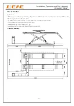
See
Annex
1
for
space
requirements
on
the
installation
site.
Step
2:
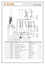
Connect
hydraulic
oil
hoses.
Connect
the
oil
hoses
to
the
power
unit
as
per
the
diagram
for
oil
hose
connection.
Annex
3.
Attention:
Connect
as
per
the
marks
on
the
hoses
and
do
not
contaminate
the
hydraulic
components
during
the
connection.
Step
3:
Connect
pneumatic
hoses.
Connect
the
pneumatic
release
system
by
the
diagram
of
air
hose
connection
in
Annex
4.
Attention:
Connect
as
per
the
marks
on
the
hoses
and
do
not
contaminate
the
pneumatic
components
during
the
connection.
Step
4:
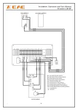
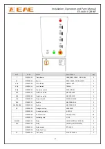
Connect
electrical
wires.
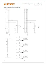
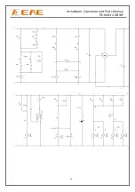
Refer
to
the
electrical
connection
scheme.
Connect
the
power
supply
and
the
quick
connecters
for
limit
switch.
(For
three
phase
power
supply
,if
the
lift
doesn't
raise
and
the
motor
may
turn
in
the
wrong
direction,
in
such
event,
interchange
wires
U,
V
in
the
control
cabinet)
.
Step
5:
Fill
with
hydraulic
oil.
ONLY
CLEAN
AND
FRESH
OIL
ONLY
.Lift
must
be
fully
lowered
before
changing
or
adding
hydraulic
oil.
Normally
it
needs
22
liters
of
hydraulic
oil.
Initially,
fill
the
tank
full
with
about
18L
of
hydraulic
oil
.
Run
the
lift
for
several
cycles
and
add
another
4L
into
the
tank.
The
level
of
oil
shall
reach
the
tippets
volume
mark
of
the
tank.
Run
the
lift
for
several
cycles
and
add
more
oil
until
the
lifting
platform
can
reach
its
maximum
height.
Note
:
As
running
speed
of
the
lift
is
mainly
decided
by
the
viscosity
of
the
hydraulic
oil,
we
suggest
using
NO.46
hydraulic
oil
when
average
temperature
of
the
location
is
above
18
degree
Celsius
and
using
NO.32
hydraulic
oil
when
temperature
is
below
18
degree
Celsius.
Change
the
oil
6
months
after
initial
use
and
change
once
per
year
thereafter.
Step
6:
Levelling
Check
the
connection
of
the
hydraulic
and
electrical
system
before
levelling
operation
Review
operation
instructions
and
get
familiar
with
lift
controls
by
running
the
lift
through
a
few
cycles
before
levelling
opearion.
Attention:
Level
the
platforms
before
connecting
max
height
limit
switch
because
if
not,
platforms
may
not
rise
to
the
highest
position.
The
operator
needs
to
know
clear
which
levelling
valve
controls
which
platform.
This
could
be
judged
by
the
way
that
the
oil
hose
was
connected
or
by
trial
raising
or
lowering.
Check
the
connection
of
the
hydraulic
and
electrical
system
before
levelling
operation
Review
operation
instructions
and
get
familiar
with
lift
controls
by
running
the
lift
through
a
few
cycles
before
leveling
opearion.
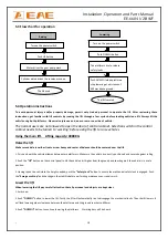
Levelling
the
main
lift.
1)Turn
on
the
main
power
switch
and
turn
the
selection
switch
SA2
to
the
main
lift
and
SA1
to
“Levelling”
status.
Turn
the
two
handles
of
levelling
valve
to
the
following
status.
Содержание EE-6604V2 .BWF
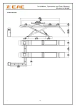
Страница 10: ...Installation Operation and Parts Manual EE 6604 V2 BWF 10 3 3 Dimensions...
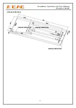
Страница 23: ...Installation Operation and Parts Manual EE 6604 V2 BWF 23 2 Recessed Mounting...
Страница 24: ...Installation Operation and Parts Manual EE 6604 V2 BWF 24 Annex 2 Electrical schemes and parts list...
Страница 25: ...Installation Operation and Parts Manual EE 6604 V2 BWF 25...
Страница 26: ...Installation Operation and Parts Manual EE 6604 V2 BWF 26...


