


® 8k/4k CL Color
26
e2v semiconductors SAS 2014
6.3.2
Image Format
Sensor Width
(
SensorWidth
) :
Get the physical width of the Sensor. This value is available in the CommCam “Image
Format Control” section :
Read function : “r snsw”;
Return by the sensor : Integer 8192.
Can not be written;
Sensor Height
(
SensorHeight
) :
Get the physical height of the Sensor. This value is available in the CommCam “Image
Format Control” section :
No Access. Virtual command in xml”; Value always = 1
Width Max
(
WidthMax
) :
Get the Maximum Width of the Sensor. This value is available in the CommCam “Image Format
Control” section :
No Access. The value is mapped on “SensorWidth”
Height Max
(
HeigthMax
) :
Get the Maximum height of the Sensor. This value is available in the CommCam “Image Format
Control” section :
No Access. Virtual command in xml”; Value always = 1
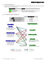
Output mode
(
OutputMode
) :
Set the CameraLink Output mode (refer also to Chapter : CameraLink Output
Configuration). This command is available in the CommCam “Image Format Control” section :
Read function : “r mode”;
Returned by the camera : Output mode from 0 to 3 (see table below).
Write function : “w mode” <value> :
detailed in the table below :
Modes
Connector CL1
Connector CL2
Mode value
Base 3 Channels RGB 8 bits
3 x 8 bits
-
0
Dual Base 3 Channels RGB 8 bits
3 x 8 bits
3 x 8 bits
1
Full 8 Channels 8bits
8 x 8 bits
2
Full+ 10 Channels 8bits
10 x 8 bits
3
“0” : BaseRGB8bits
“1” : DualBaseRGB8bits
“2” : RawFull8Outputs8bits
“3” : RawFullPlus10Outputs8bits
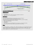
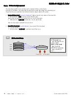
Switching between Sensor modes
The “Raw” output modes (8 or 10Taps) are achieved by loading another FPGA firmware. Then the switch
time between Base or Dual Base modes and Full 8taps or Full+ 10Taps mode is about several seconds
(maximum 9s). When these output modes are activated, the Color selection (see below p29) is no more
possible.


