


_______________________________________________________________________________________________________________________________
European Safety Systems Ltd.
Impress House, Mansell Road, Acton, London W3 7QH [email protected] Tel: +44 (0)208 743 8880
www.e-2-s.com Fax: +44 (0)208 740 4200
Document No. D202-00-001-IS Issue 1 25-04-2022 Sheet 6 of 7
stage or added to the correct terminal blocks afterward. All
devices must comply with the requirements stipulated in
section 15.
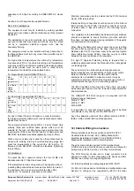
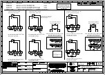
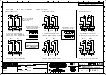
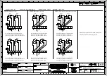
Electrical Connections are to be made into the terminal
blocks using solid or stranded wire.
Wires having a cross sectional area between 0.5 mm² to
2.5mm² (AWG 20 – 14) can be connected to each terminal
way.
If an input and output wire is required the 2-off Live/Neutral or
+/- terminals can be used. If fitting 2-off wires to one terminal
way the sum of the 2-off wires must be a maximum cross
sectional area of 2.5mm².
Strip wires to 8mm. Wires may also be fitted using ferrules.
Terminal screws need to be tightened down with a tightening
torque of 0.45 Nm / 5 Lb-in.
When connecting wires to the terminals great care should be
taken to dress the wires so that when the cover is inserted
into the chamber the wires do not exert excess pressure on
the terminal blocks. This is particularly important when using
cables with large cross sectional areas such as 2.5mm².
13) Testing unit operation
The break glass unit can be tested without the need to
break/replace the frangible glass element.
A test key (Plastic Key Supplied with unit) is used to
mechanically drop the glass down activating the switch.
The test key is inserted in the test cam and rotated clockwise
by an angle of 90º the glass element will visibly drop down in
the viewable window.
The call point switch will now change over its contacts to
operate the alarm.
Once testing is complete the unit needs to be reset, the test
key is rotated back anticlockwise 90º to its original vertical
position. The glass element should now raise up so it is level
again (horizontal) in the viewable window.
1. 2. 3.
Insert test
Hold in Rotate back
Key rotate
position anticlockwise
clockwise
during to reset
60º
test
14) Replacement of glass element
If the break glass unit has been operated the broken glass
element can be quickly replaced.
The break glass cover plate is removed by unscrewing the 4
off M4 cap head screws attaching it.
Once the cover is removed the broken glass will be free to be
removed, clean out any other fragments of glass carefully.
To fit the new glass element rotate the test cam clockwise by
an angle of 90º (use test key supplied) this will than allow the
glass to fit back into the pocket it sits in, resting on the pivot
point and test cam, ensure the plunger shaft is resting on the
top of the glass, it might need to be pushed up slightly to
achieve this.


