_______________________________________________________________________________________________________________________________
European Safety Systems Ltd.
Impress House, Mansell Road, Acton, London W3 7QH [email protected] Tel: +44 (0)208 743 8880
www.e-2-s.com Fax: +44 (0)208 740 4200
Document No. D202-00-001-IS Issue 1 25-04-2022 Sheet 7 of 7
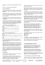
Pivot point Test Cam Plunger Rotate test cam back
Shaft
Upright set point
Whilst lightly holding the glass in place rotate the test cam
back anticlockwise 90º to its original vertical position. The
glass element should now raise up so it is level again
(horizontal) in the viewable window.
Replace the cover plate and tighten the 4 off M4 cap head
screws.
Ensure the glass element is free to move under the cover
plate. This can be done by running through the units test
operation. See section 13 of this instruction manual.
15) End-of-Line and Series Devices
All models can be fitted with series resistors, end-of-line
monitoring resistors, monitoring diodes and zener diodes if
supplied with direct current up to 48Vdc and limited to a
maximum total power consumption no greater than 6.224W.
Min. resistor values and current limitations must be observed
depending on supply voltage and type of components fitted. If
a combination of resistors / diodes / zener diodes is used,
values for all components must be observed and lowest
current limit for either component becomes overall limit.
Current limitation for units fitted with end-of-line resistors,
diodes or zener diodes must be ensured by using a current
limited power supply or fitting a current limiting resistor at the
control panel (not provided).
The following table 2 shows limitations for all possible
variations:
EOL (End of line) device;
resistor – ExxxR
diode – ED1
zener – ExxxZ
Series (In line) device;
resistor – SxxxR
diode – SD1
zener – SxxxZ
LED
Microswitch 1 = M/S 1
Microswitch 2 = M/S 2
Table 2 : EOL and Series Devices limits
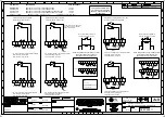
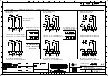
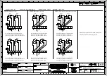
The unit can be wired with a maximum of 4 module devices –
see wiring diagram D202-06-211
Note:- The maximum voltage stated must not be exceeded,
as the internal resistor modules are rated as compliant with
Ex d according to the units voltage
16) Maintenance, Overhaul, Repair and
Cleaning
Maintenance, repair and overhaul of the equipment should
only be carried out by suitably qualified personnel in
accordance with the current relevant standards:
For ATEX / IECEx / UKEx
For US & CEC Class / Div / Zone
UL 60079-19
Explosive atmospheres - Equipment repair,
overhaul and reclamation
UL
60079-17
Explosive atmospheres - Electrical
installations inspection and maintenance
Electrostatic charging hazard – clean only with a damp cloth.
Units must not be opened while an explosive atmosphere is
present.
Caution do not change factory applied finishes
Supply voltage 24Vdc Supply voltage 48Vdc
Type of
component
fitted
value Max.
current
(mA)
value Max.
current
End-of-Line
Resistor
*See note
min. 470R/
2W or min.
2k2 / 0.5W
3000
min. 2k2 /
2W or min.
8k2 / 0.5W
1000
End-of-Line
Diode
Type 1N5401
2W 59.13
2W 25.26
Series
Resistor
*See note
min. 470R/
2W or min.
2k2 / 0.5W
3000
min. 2k2 /
2W or min.
8k2 / 0.5W
1000
Series Diode
Type 1N5401
2W 59.13
2W 25.26
Series Zener
Diode Type
1N5333B
3.3V 230
3.3V 230
4.7V 162
4.7V 162
5.1V 149
5.1V 149
5.6V 136
5.6V 136
6.2V 122
6.2V 122
6.8V 112
6.8V 112
10V 76
10V 76
12V 63
12V 63
EN60079-19
IEC60079-19
Explosive atmospheres - Equipment repair,
overhaul and reclamation
EN 60079-17
IEC60079-17
Explosive atmospheres - Electrical
installations inspection and maintenance


