_______________________________________________________________________________________________________________________________
European Safety Systems Ltd.
Impress House, Mansell Road, Acton, London W3 7QH [email protected] Tel: +44 (0)208 743 8880
www.e-2-s.com Fax: +44 (0)208 740 4200
Document No. IS 2441-P Issue G 19-03-10
Sheet 5 of 6
16)
End of Line Monitoring (DC Units)
On BExCS110-05D DC units, dc reverse line monitoring can
be used if required. All DC units have a blocking diode fitted
in their supply input lines on both the sounder section and the
beacon section. An end of line monitoring diode or an end of
line monitoring resistor can be connected across the +ve and
–ve terminals. If an end of line resistor is used it must have a
minimum resistance value of 3k3 ohms and a minimum
wattage of 0.5 watts or a minimum resistance value of 500
ohms and a min. wattage of 2 watts. If the sounder and
beacon sections are wired to separate power supplies then
an end of line monitoring component can be used in each
section.
17)
Synchronised Operation
All BExCS110-05D units that are connected to the same
supply line will have a synchronized sound output and a
synchronised flash rate at one flash every second. To ensure
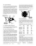
that the units will be synchronised check that the pin header
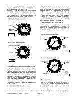
is not fitted, i.e. the two header pins are not shorted together
(see Figures 4 and 5).
18)
Flip / Flop Operation
Two units can be mounted close to each other to form a flip-
flop operation, where the beacons will flash alternately. To
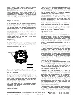
achieve this mode of operation, fit a pin header to the flip-
flop header pins on the electronics board, i.e. the two header
pins are shorted together, (see figures 4 and 5) on one of the
two beacons. The first flash on the beacon that has the
header fitted will be delayed by ½ second. The two beacons
will then flash alternately every ½ a second.
TONE SELECTION TABLE
Tone Selection
DIP Switch
Settings
Stage Selection
Stage 1
Frequency Description
1 2 3 4 5
Stage 2
Stage 3
1
Continuous 1000Hz
Toxic gas alarm
0 0 0 0 0
Tone 31
Tone 11
2
Alternating 800/1000Hz at 0.25s
intervals
1 0 0 0 0
Tone 17
Tone 5
3
Slow Whoop 500/1200Hz at 0.3Hz
with 0.5s gap repeated
0 1 0 0 0
Tone 2
Tone 5
4
Sweeping 800/1000 at 1Hz
1 1 0 0 0
Tone 6
Tone 5
5
Continuous at 2400Hz
0 0 1 0 0
Tone 3
Tone 27
6
Sweeping 2400/2900Hz at 7Hz
1 0 1 0 0
Tone 7
Tone 5
7
Sweeping 2400/2900Hz at 1Hz
0 1 1 0 0
Tone 10
Tone 5
8
Siren 500/1200/500Hz at 0.3Hz
1 1 1 0 0
Tone 2
Tone 5
9
Sawtooth 1200/500Hz at 1Hz
0 0 0 1 0
Tone 15
Tone 2
10
Alternating 2400/2900Hz at 2Hz
1 0 0 1 0
Tone 7
Tone 5
11
Intermittent 1000Hz at 0.5Hz
General alarm
0 1 0 1 0
Tone 31
Tone 1
12
Alternating 800/1000Hz at 0.875Hz
1 1 0 1 0
Tone 4
Tone 5
13
Intermittent 2400Hz at 1Hz
0 0 1 1 0
Tone 15
Tone 5
14
Intermittent 800Hz 0.25s on 1s off
1 0 1 1 0
Tone 4
Tone 5
15
Continuous at 800Hz
0 1 1 1 0
Tone 2
Tone 5
16
Intermittent 660Hz 150mS on,
150mS off
1 1 1 1 0
Tone 18
Tone 5
17
Alternating 544Hz
(100mS)/440Hz(400mS)
0 0 0 0 1
Tone 2
Tone 27
18
Intermittent 660Hz 1.8s on, 1.8s off
1 0 0 0 1
Tone 2
Tone 5
19
1400Hz to 1600Hz sweep up over
1s - 1600Hz to 1400Hz sweep down
over 0.5s
0 1 0 0 1
Tone 2
Tone 5
20
Continuous 660Hz
1 1 0 0 1
Tone 2
Tone 5
21
Alternating 554/440Hz at 1Hz
0 0 1 0 1
Tone 2
Tone 5
22
Intermittent 554Hz at 0.875Hz
1 0 1 0 1
Tone 2
Tone 5
23
800Hz pulsing at 2Hz
0 1 1 0 1
Tone 6
Tone 5
24
Sweeping 800/1000Hz at 50Hz
1 1 1 0 1
Tone 29
Tone 5
25
Sweeping 2400/2900Hz at 50Hz
0 0 0 1 1
Tone 29
Tone 5
26
Simulated bell sound
1 0 0 1 1
Tone 2
Tone 1
27
Continuous 554Hz
0 1 0 1 1
Tone 26
Tone 5
28
Continuous 440Hz
1 1 0 1 1
Tone 2
Tone 5
29
Sweeping 800/1000Hz at 7Hz
0 0 1 1 1
Tone 7
Tone 5
30
420Hz repeating 0.625s on, 0.625s
off
Australian alert signal
1 0 1 1 1
Tone 32
Tone 5
31
1200/500Hz at 1 Hz
Prepare to abandon platform
0 1 1 1 1
Tone 11
Tone 1
32
Sweeping 500/1200Hz 3.75s on,
0.25s off 15Hz
1 1 1 1 1
Tone 26
Tone 1
Unit No. 2
+
+
-
S2
S3
-
Sounder
PCB
+ -
S2
S3
Unit No. 1
Beacon
PCB
+ -
+ -
Beacon
PCB
Beacon
PCB
+ -
Sounder
PCB
+ -
S2
S3
Sounder
PCB
+ -
S2
S3
Unit No. 3
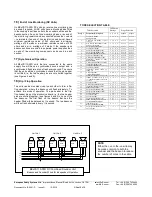
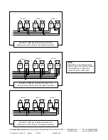
BExCS110-05D DC Combined Sounder Unit
Beacon and Sounder Wired for Independent Operation
NOTE
Either the +ve or the -ve wire may
be made common to both the
sounder and the beacon to reduce
the number of cores in the cable.


