_______________________________________________________________________________________________________________________________
European Safety Systems Ltd.
Impress House, Mansell Road, Acton, London W3 7QH [email protected] Tel: +44 (0)208 743 8880
www.e-2-s.com Fax: +44 (0)208 740 4200
Document No. IS 2441-P Issue G 19-03-10
Sheet 2 of 6
6)
Location and Mounting
The location of the unit should be made with due regard to
the area over which both the sounder and beacon warning
signal must be audible and visible. The unit should only be
fixed to services that can carry the weight of the unit.
The unit should be securely bolted to a suitable surface using
the 7mm diameter boltholes in the stainless steel U shaped
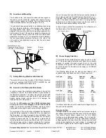
mounting bracket (see figure 1). The angle can then be
adjusted in the direction such that its warning signals can be
both heard and seen. This can be achieved by loosening the
two large bracket screws in the side of the unit, which allow
adjustment in steps of 18
°
. On completion of the installation
the two large bracket adjustment screws on the side of the
unit must be fully tightened to ensure that the unit cannot
move in service.
7)
Safety Warning (Electrostatic Hazard)
The acoustic horn section is made of ABS Plastic, therefore
to avoid a possible ELECTROSTACTIC CHARGE the unit
must only be cleaned with a damp cloth.
8)
Access to the Flameproof Enclosure
In order to connect the electrical supply cables to the unit it is
necessary to remove the beacon section to gain access to
the flameproof chamber. To achieve this remove the four M6
hexagon socket head screws (see figure 2) and withdraw the
beacon section taking extreme care not to damage the
flameproof joints in the process.
Note the four
M6 screws are Class A4-80 stainless steel
and only screws of this category can be used on these
units.
It is therefore important that these screws and their
spring washers are kept in a safe place during installation.
On completion of the cable wiring installation the flameproof
joints should be inspected to ensure that they are clean and
that they have not been damaged during installation. Also
check that the earth bonding wire between the two casting
sections is secure and the ‘O’ ring seal is in place. When
replacing the beacon section casting, ensure that it is square
with the sounder section chamber casting before inserting.
Carefully push the beacon section in place allowing time for t
the air to be expelled. Only after the beacon section casting is
fully in place should the four M6 Stainless Steel A4-80 cover
bolts and their spring washer be inserted and tightened
down. If the beacon section jams while it is being inserted,
carefully remove it and try again. Never use the cover bolts to
force the beacon section casting into position.
In case of repair, contact the manufacturer for information on
the dimensions of the flameproof joints.
9)
Power Supply Selection
It is important that a suitable power supply is used to run the
unit. The power supply selected must have the necessary
capacity to provide the input current to all of the units
connected to the system The sounder and beacon sections
can both be wired to the same power supply or to different
power supplies
The following table shows the input current taken by the
sounder section and beacon section of the various units:-
Unit Type
Input
Sounder
Max.
Voltage
Current I/P Volts
BExCS110-05D
24V DC
265mA
30V
BExCS110-05D
12V DC
195mA
15V
BExCS110-05D
48V DC
130mA
58V
BExCS110-05D
230V AC
56mA
264V
BExCS110-05D
115V AC
110mA
126V
Unit Type
Input
Beacon
Max.
Voltage
Current I/P Volts
BExCS110-05D
24V DC
300mA
30V
BExCS110-05D
12V DC
750mA
15V
BExCS110-05D
48V DC
180mA
58V
BExCS110-05D
230V AC
55mA
264V
BExCS110-05D
115V AC
140mA
126V
The above table also shows the maximum voltages at which
the units can be operated.
Sounder Section
The input current to the sounder section will vary according to
the voltage input level and the frequency of the tone selected.
The current levels shown above are for the 440Hz
Continuous tone @ nominal input voltage. The 24V and 48V
DC units and the 230V AC, 115V AC units have a switching
voltage regulator circuit and therefore the input current level
will decrease slightly as the input voltage in increased and
will increase slightly as the input voltage is reduced. The 12V
S/S Mounting
Bracket
Sounder
Section
Flashdome
Guard
Plastic Acoustic Horn
Please see Safety Warning
In Section 7 of this manual
Fig 1
Beacon
Section
4 off Cover Screws
External Earth
Terminal
Fig 2


