10
Settings
1.
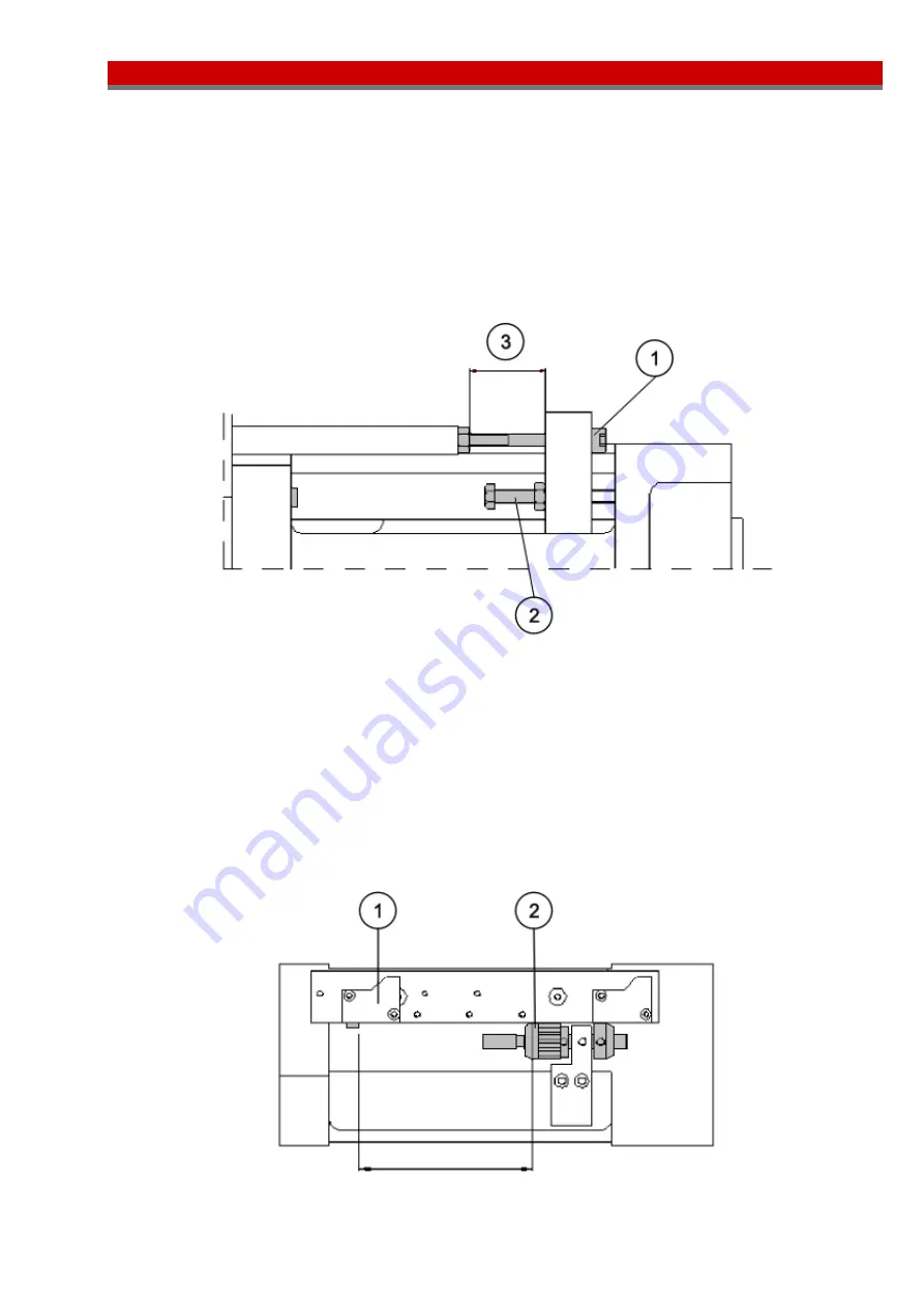
Transition from rapid advance to working feed.
Setting the transition on units equipped with pneumatic, electrical or proximity limit switches is
performed with a screw, see Fig. 12, Pos. 1, which on return of the feed spindle, retracts the hydrocheck
piston rod into position for the next braking. To make it possible to set the transition along the entire
stroke length, the unit is delivered with two separate screws of different lengths.
When setting or changing the screw, the feed spindle must be advanced. If this is done using the units
compressed air system, the system must be depressurized before setting or changing the screw.
For units fitted with a linear transducer, the hydrocheck piston rod is fixed by screw to the adapter and
this follows the movement of the feed spindle completely. Setting is performed using the external
control system.
Fig. 12.
2.
Drilling depth and forward-reverse position.
For units with pneumatic, electrical or proximity limit switches, the reverse position is set by first making
a coarse setting by placing the position sensor, see Fig. 13, Pos. 1, in the right position (4 positions).
Then place the cam, see Fig. 13. Pos. 2, in the right groove on the rod. The cam is locked into the
groove with a screw. In certain positions the threaded portion of the cam must be screwed out to expose
the screw. Setting is then accomplished with the threaded cam. One rotation corresponds to 1 mm
(.039 In). See Fig. 13.
For units with a linear transducer, drilling depth and the forward-reverse position are set using the
external control system and the analog signal from the position sensor.
Fig. 13.
Содержание BE 481
Страница 18: ...18 Spare parts drawing ...
Страница 23: ...23 Spare parts drawing ...


