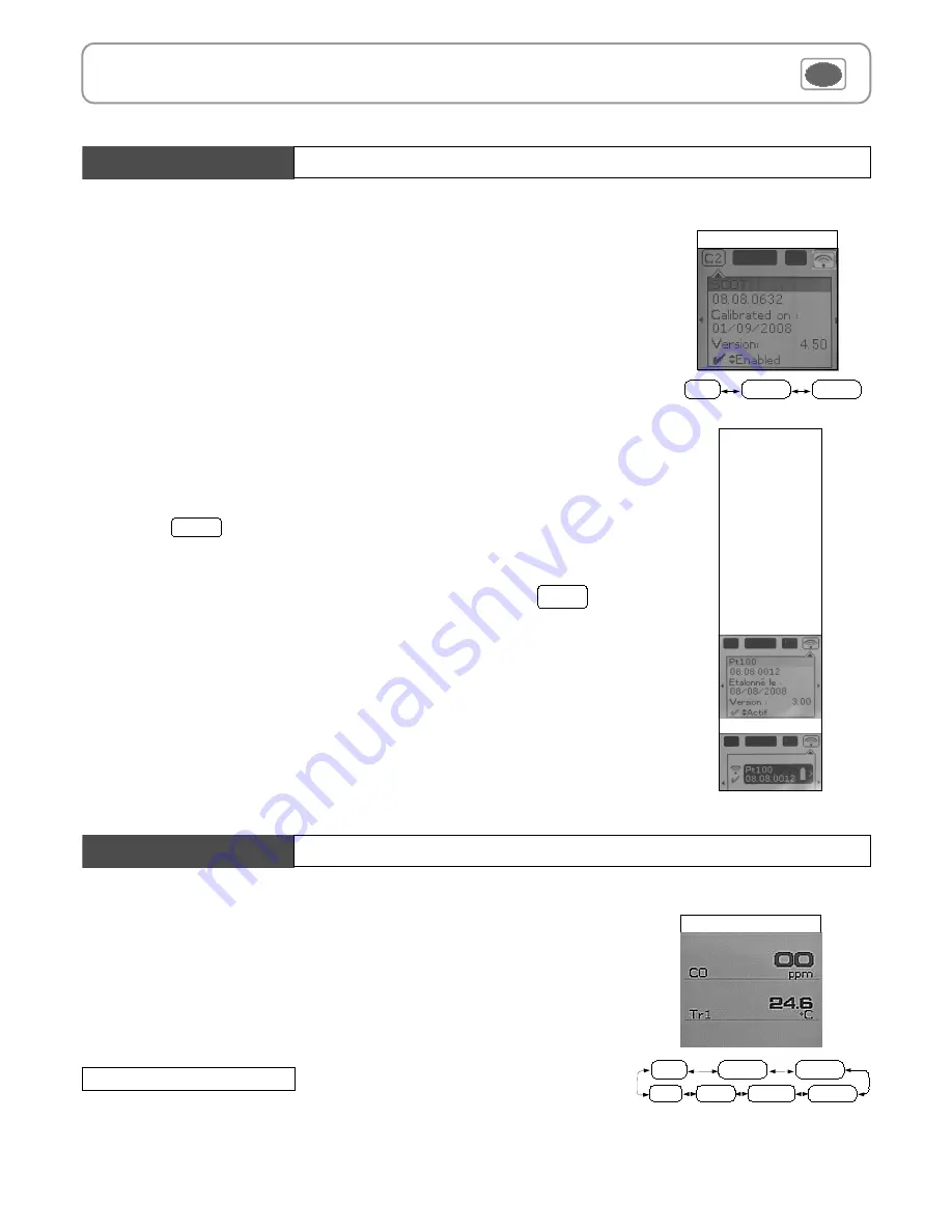
Probe menu
The following functions are enabled only if at least one probe is connected.
You can access to the following sub-functions :
- Hold - Min/Max
- Configuration
- Delta T
- Parameters
- Calculation
- Recording
8
IV – Menus
Infos
Measure
Probe display
Params
Functions
Hold- Min./Max.
Press 1x in order to select
HOLD
function : measurement holding on display.
Press 2x in order to select
Min-Max
function : display of minimum and maximum values.
Press 3x : back to the continuous measurement.
Measurement display
Rec.
Hold
Config
Delta T
Params
Probe
Alarms
Sondes RF
RF probes display
RF probes searching
RF probes detected
RF probes display
1. Using wire probes and modules
Wire probes and modules with Smart-plus system are automatically recognized from first connection.
The ''
Probe
''
menu only appears when probes or module are connected. This menu allows to view probe
information plugged to
C2, Module, C1
or
wireless connections
.
(See « Connections » p 6 for more information about connections).
Available information are :
•
Sensor type, Serial number, Date of last calibration or adjustement, Probes Status (enabled ou
disabled).
On enabled mode, the probe is connected, the measurement is carried out and the value is displayed.
On disabled mode, the probe is connected, the measurement is not carried out and the value is not
displayed.
2. Using wireless communication
A- Add a wireless probe
A1. Go to probe menu by pressing ''
Probe
'' access key.
A2. With arrow keys
and
, go to ''
RF probes
'' display.
A3. Select
New
with access key.
A4. Power up the probe and press multifunction button until LED blinks. Once the probe is
recognized, information appears.
Left button
allows to return to the wireless probes display and to access all wireless probes
already recognized by the instrument. With access keys, it is possible to delete
a wireless
probe.
B- Select a wireless probe already created.
B1. Power up the wireless probe (short press on Multifunction button).
B2. Go to ''
Probe
''
menu.
B3. With arrows keys
and
, go to ''
RF probes
'' display. All the wireless probes already
recognized appear.
B4. Select the suitable wireless probe with
or
.
B5. Go to probe informations using arrow key
.
B6. Enable the wireless probe with arrows keys
and
and confirm with
OK
.
Del
Содержание AQ 200
Страница 1: ...AQ 200 AQ 200 Air Quality...
Страница 4: ...5 Description II Introduction...


