User Manual
EE381
Page 10
5. Operating Components
5.1 Circuit Board
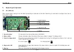
After removal of the housing cover, the following operating components on the circuit board may be accessed to configure the sensor to
the desired settings:
1. Serial interface:
Pin connector for serial interface cable (HA010604).
2. Status LEDs:
Provide information about the status of the device. Refer to chapter
“
5.2 Status LEDs”.
3. Current-/ voltage output:
If the sensor is switched from current to voltage output, using the configuration software, the 2 jumpers
must be positioned accordingly:
for current signals:
for voltage signals:
4. Diagnostic LED:
Visual indication for easy determination of the cause of error. (refer to chapter “6.2 Self-diagnosis and
Error Messages”).
5. Display:
These pin connectors are designated for the display module.
I
U
I
U
I
U
I
U
5. Display
2. Status LEDs
3. Current / voltage output
1. Serial interface
4. Diagnostic LED


