


- Water and gas supply connections between the boiler and the mounting bracket can be fixed with the optional
pipes and the nipples as shown in Figure 1
2
.
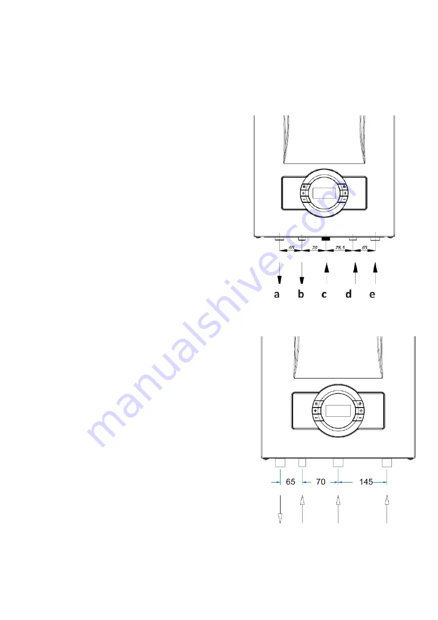
a) CH flow ¾ ‘’ (hot)
b) DHW outlet ½ ‘’ (hot)
c) Gas inlet ¾’’
d) DHW inlet ½ ‘’ (cold)
e) CH return ¾’’ (cold)
-A suitable valve should be mounted on the gas inlet and CH &
DHW water circuit. In addition, a water filter should be mounted
on CH (3/4”) return and DHW (1/2”) inlet.
- A plastic pipe should be fixed the outlet tap of the three bar
relief valve and the pipe should be connected to the drain line.
- The connection between the appliance and gas supply must
be made with a flexible pipe.
- National and local requirements should be take into
consideration.
Figure 12
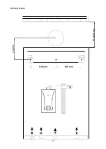
9.2.2- HCH Model
a
b
C
d
a)
CH flow ¾ ‘’ (hot)
b) Water filling
line
1/2"
c)
Gas inlet ¾’’
d)
CH return ¾’’ (cold)
Figure 13
9.2- Gas and Water Connections
9.2.1- H
M
Model
18
Содержание Proteus Premix PPR 14 HCH
Страница 9: ...5 4 Technical Specifications 9 ...
Страница 10: ...10 ...
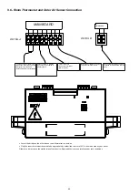
Страница 11: ...5 5 Electrical Drawing Figure 4 Boiler sensor in HST model Except of HCH Model Only HM Model 11 ...
Страница 28: ...28 ...
Страница 29: ...Table 4 29 ...
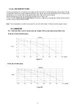
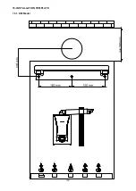
Страница 32: ...16 INSTALLATION TEMPLATE 16 1 HM Model 32 ...
Страница 33: ...E E L C 160 mm 00 160 mm cJiD E E o o L C E 16 2 HCH Model 33 ...
Страница 34: ...E E L C 160 mm 00 C 160 mm E E o o L C E 16 2 HST Model 34 ...
Страница 36: ...36 ...
Страница 37: ...37 ...
Страница 38: ...38 ...
Страница 39: ...39 ...
Страница 41: ...41 ...


