


Dytran Instruments, Inc. 21592 Marilla St. Chatsworth, CA 91311 Phone: (818) 700-7818 Website:
email: [email protected]
Page | 18
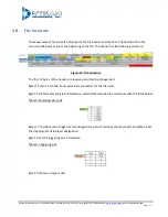
Table 5: Run Type
Bytes 21 and 22 have battery level information at the beginning of the file creation. The 12-bit number
corresponds to the output of the ADC. The number has 2048 offset and can be converted to the actual
battery voltage using the following formula:
V
bat
= (BatteryLevel – 2048)* 0.002170
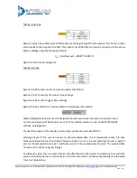
Byte 23 is the file size designator
Table 6: File size
Bytes 24 to 29 contain model and serial number information
Bytes 32 to 37 contain Synchronous Time settings
Bytes 48 to 53 contain Trigger Time settings
Bytes 38 to 45 and 54 to 57 contain offset and sensitivity information
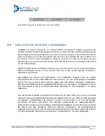
Master(0)/Slave(1) selector used to designate master versus slave operation mode when used
synchronously (when SYNCH byte is set to 1). When SYNCH selector is at 0, the MASTER/SLAVE
settings is disregarded.
The last three bytes of the header contain static verification code 0x071A51h
Starting at byte 97 the user can access an actual sampled data. The sampled data comes in 8 byte
blocks with Byte 0 and 1 of each block being 0s, bytes 2 and 3 is the sampled data for axis X, bytes 4
and 5 is the sampled data for axis Y, and bytes 6 and 7 is the sampled data for axis Z. The sampled data
for each axis is 16-bit unsigned integer.
To display the data, the user must subtract the offset found in the header and divide by the sensitivity
value and multiply by the correction factor. The correction factor is obtained by dividing the U16 value
from the fields below:


