background image

Fitting notes

Service manual

82

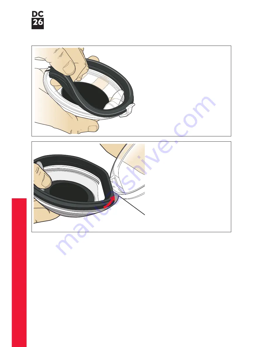
  The bin base seal and FDC seal 

can be replaced by firmly pulling 

out of the bin base assembly. 

When fitting ensure all seals are 

adequately seated.

83

  To locate the bin base assembly, 

locate one of the legs on the 

assembly onto the hinge point 

on the bin. 

Once located firmly press the 

other leg into place.

 36

Содержание DC26

Страница 1: ...Service manual Issued September 09 ...

Страница 2: ... rewind assembly inspection Electrical safety testing Wiring schematic Resistance values Electrical fault diagnosis Main chassis and motor assembly Main body parts Cyclone and bin assemblies Handle hose and floor tool Contents This manual is written specifically for Dyson trained engineers and covers the full DC26 range The service instructions assume the engineer has the approved tools and test e...

Страница 3: ...ectly to it for cleaning awkward places Cleaner exhaust air Releases air containing 150 times less mould and bacteria than the air you breathe Miniaturised cable rewind Smaller and lighter without compromising cable length of 5m Centralised motor Positioned to reduced drag weight Makes the machine easier to pull along Small and compact Fits on an A4 sheet of paper Easy to carry and store Lightweig...

Страница 4: ...ill require replacement of the chassis and motor assembly The Seaward Primetest 200 or equivalent should be used to test the electrical insulation of a Class 11 appliance it indicates any electrical leakage Insulation test point These tests are vital to avoid any possibility of personal injury to the end user If you cannot repair a product with an insulation test reading of below 2MW you must info...

Страница 5: ...ch Cyclone inlet Contacts 1 2 3 5 7 9 10 8 4 6 COMPONENT POWERCORD ASSY 1 2 5 POWERCORD ASSY POWERCORD TO MAIN ON OFF SWITCH MAIN CHASSIS AND MOTOR ASSY WITH CABLE REWIND ATTACHED WITH CABLE REWIND REMOVED MAIN ON OFF SWITCH TEST BETWEEN POINTS OHMS 3 4 7 TO 1 Ω MAX 1 Ω MAX 1 Ω MAX 6 Ω APPROX 1 Ω MAX 1 2 TO 7 8 TO 9 10 TO TO TO ...

Страница 6: ...tor housing and check that the wires are attached to the On Off switch points 7 and 8 6 Check the mechanical actuation of the On Off switch 7 Carry out a resistance test across the switch points 9 10 ensuring the switch is in the On position 8 Remove the cable wiring retainer assembly from the product see pages 38 and 39 for instructions and check that the Live point 5 wire from the On Off switch ...

Страница 7: ...ip will need to be activated before separation from the male terminal can occur Ensure that safety goggles are worn where this symbol is shown Cable rewind removal Recommended tools to repair DC26 Torx T 8 T 10 T 15 screwdrivers Large flat bladed screwdriver Thin flat bladed screwdriver Long needle nosed pliers 05 01 Remove the cyclone and bin assembly from the product Wire colours may vary betwee...

Страница 8: ...Fitting notes Service manual 06 02 Undo the two fasteners in the post filter cover assembly 03 Remove the cover 04 Pull the hose retainer catch to release the hose from the base of the product ...

Страница 9: ...ng notes Service manual 07 05 Firmly release the hose from the cyclone inlet 06 Firmly pull the wheel and retainer off the cable rewind side of the product 07 Undo the three screws in the cable rewind cover ...

Страница 10: ...wind assembly Prise the cable protector off the side of the chassis 10 Important press the cable rewind actuator and allow the cable rewind assembly to turn through two revolutions clockwise to remove any remaining tension in the cable spring assembly Failure to do this could result in injury when removing the spring assembly x2 ...

Страница 11: ...ce manual 09 13 Remove the cable rewind assembly from the side of the product 12 Carefully remove the spring assembly from the cable rewind assembly 11 Undo the T 15 screw in the middle of the cable rewind spring assembly ...

Страница 12: ...e product Failure to do so will result in the cable not adequately rewinding 15 Lower the cable rewind assembly onto the spindle in the chassis 16 Ensure the entire length of cable is wound onto the cable rewind assembly Locate the cable rewind spring assembly onto the cable rewind any one of three orientations Fit the screw Cable rewind fitting ...

Страница 13: ...he drum of the cable rewind 17 Turn the drum of the cable rewind assembly by hand anti clockwise through two revolutions This will pre set the spring with two turns Failure to do this may result in a poorly performing cable rewind assembly 19 Fit the cable protector x2 ...

Страница 14: ...e cable rewind for adequate actuation before continuing If unsatisfactory repeat steps 14 19 20 Locate the cable rewind cover onto the side of the chassis 22 Locate the wheel onto the side of the chassis Align the snaps on the wheel retainer with the details on the product Fitting notes 12 ...

Страница 15: ... chassis Press the hose retainer onto the chassis until the release catch clicks into position Hook detail Hose retainer 23 Firmly press the retainer into position ensuring each of the snaps locate 24 Slide the hose into the cyclone inlet Ensure it is pushed in as far as possible ...

Страница 16: ... 27 Fit the post filter cover assembly ensuring the tab details on the rear of the cover locate under the chassis Tighten the two fasteners 26 Fit the post filter assembly 14 28 Locate the cyclone and bin assembly onto the product ...

Страница 17: ...T 15 screw in the stow bracket 30 Carefully release one side of the stow bracket away from the chassis to release it Repeat on the other side 31 Carefully slide a thin flat bladed screwdriver between the switch actuator and switch housing where shown Carefully prise the actuator out of the housing Remove the spring ...

Страница 18: ...32 Repeat for the other actuator ensuring the screwdriver is inserted exactly where shown Failure to insert it where shown may result in damage to the actuator housing 34 Firmly remove the actuator housing 33 Undo the two T 15 screws ...

Страница 19: ...notes Service manual 17 37 Carefully detach the wires from the switch 36 Remove the glass cloth tape from the terminal boots Put to one side for re use 35 Carefully release the switch and wires from the chassis ...

Страница 20: ...d Note if the glass cloth tape is unusable it will be necessary to cut a length approximately 60mm off a roll Position the switch onto the chassis ensuring the terminal boots sit behind the wall section Neatly dress the switch wires into the channel provided 39 Slide the actuator housing onto the chassis until it clicks into position 40 Fit the two T 15 screws Switch fitting ...

Страница 21: ...Fitting notes Service manual 19 41 Fit each actuator ensuring the springs are positioned under the cruciform details 42 Twist the stow bracket onto the chassis Fit the T 15 screw ...

Страница 22: ...ewind actuator and spring as previously shown page 16 step 32 44 Peel the end of the inlet seal from the chassis Note the inlet seal is spot glued in several places Undo the Torx T 8 screw 45 Prise the brake wheel stopper out of the chassis Brake wheel assy removal ...

Страница 23: ...Fitting notes Service manual 46 Prise the brake wheel housing and brake wheel assembly out of the chassis 47 Separate the brake wheel assembly from the housing if necessary 21 ...

Страница 24: ...into the brake housing Slide the housing into the chassis ensuring it locates over the retaining ribs If fitted correctly the housing will sit square within the chassis 49 Locate the brake wheel stopper into the chassis Fit the Torx T 8 screw Brake wheel assy fitting Retaining ribs 22 ...

Страница 25: ...fit the cable rewind actuator Note it is good practice to test the cable rewind for adequate actuation 50 Apply several spots of glue around the edges of the inlet Refit the inlet seal ensuring it is adequately seated in all channels 23 ...

Страница 26: ...way from the chassis 53 Remove the screw below the post filter assembly Cyclone inlet chassis and motor assembly replacement dismantle Before continuing the following parts should be removed as previously shown Cyclone and bin assembly Wand and hose Cable rewind assembly pages 5 9 24 54 Remove the screw in the side of the chassis ...

Страница 27: ...rise the cyclone inlet out of the catch detail on the side of the chassis 56 Carefully release the ESD wire and tab from the cyclone inlet 57 If replacing any of the parts attached to the cyclone inlet remove the screw in the underside of the inlet ...

Страница 28: ...Fitting notes Service manual 58 Separate the cyclone inlet from the connector housing cap 26 59 Twist the connector housing out of the connector housing cap ...

Страница 29: ...y motor or any components within the chassis it will be necessary to replace the entire chassis and motor assembly as a whole This is due to the complexity and time taken to remove and replace the motor from the chassis Chassis and motor assembly Components included within the Chassis and motor assembly ...

Страница 30: ...of the chassis using a thin flat bladed screwdriver 61 Remove the screw in the stow bracket Carefully prise one side of the stow bracket away from the chassis to release it Repeat on the other side The following components are only offered separately and will require removing from the chassis and motor assembly before fitting to the new assembly ...

Страница 31: ...Fitting notes Service manual 65 Remove the exhaust grille 64 Remove the Torx T 15 screw from the underside of the chassis 29 ...

Страница 32: ... components that make up the bleed valve into the new chassis and motor assembly in the orientation shown Fit the screws 67 Locate the exhaust grille onto the side of the chassis Fit the screw in the underside of the chassis 68 Locate the connector housing into the cyclone inlet assembly screw holes aligned ...

Страница 33: ...9 Ensure the connector housing is securely located under the tab on the inlet assembly 70 Locate the connector housing cap over the connector housing and cyclone inlet assembly 71 Fit the Torx T 15 screw in the underside of the housing ...

Страница 34: ...f the ESD wire into the end of the connector housing cap Dress the wire neatly within the channels provided 32 73 Locate the end of the connector housing cap into the slot in the front of the chassis 74 Locate the underside of the cyclone inlet assembly into the chassis ...

Страница 35: ...Fitting notes Service manual 33 75 Fit the screw in the side of the chassis 76 Fit the screw in the underside of the product 77 Twist the stow bracket onto the chassis Fit the T 15 screw ...

Страница 36: ... Locate the pre filter into the pre filter door Locate the pre filter door onto the side of the chassis After completing all the preceding steps the following parts should be fitted as previously shown Cable rewind assembly pages 10 14 ...

Страница 37: ... the spring onto the pip on the catch Firmly press both parts onto the bin 79 The front bin catch can be removed from the bin assembly by gently prising off with a thin flat bladed screwdriver 81 The bin base assembly can be removed by firmly prising off the bin assembly 35 ...

Страница 38: ...e replaced by firmly pulling out of the bin base assembly When fitting ensure all seals are adequately seated 83 To locate the bin base assembly locate one of the legs on the assembly onto the hinge point on the bin Once located firmly press the other leg into place 36 ...

Страница 39: ...mblies 85 To fit locate the spring onto the rear of the swivel catch Firmly press the catch into the retainers on the handle hose or extension tube 84 The swivel catch can be removed from the end of the handle hose or extension tube by prising off with a thin flat bladed screwdriver 37 ...

Страница 40: ...d any diagnostic checks can be carried out see page 4 for details 86 Remove the four Torx T 8 screws 88 Before refitting ensure wiring is neatly dressed within any retaining features 38 The cable wiring retainer assembly is not offered as a separate customer service spare item It can however be removed for diagnostic purposes see page 4 for details Remove the cable rewind assembly ensuring all saf...

Страница 41: ...op edge of the cable wiring retainer assembly behind the brake wheel 89 Carefully ease the lower edge of the cable wiring retainer assembly behind the bleed valve housing 91 Fit the four screws Refit the cable rewind assembly following all necessary precautions see pages 10 14 for details 39 ...

Страница 42: ...Parts recognition Service manual 40 Main chassis and motor assembly Main chassis and motor assembly ...

Страница 43: ...er Assy Connector Housing Cylone Inlet Assy Screw Catch Pre filter Door Assy Wheel Wheel Retainer Bleed Valve Housing Bleed Valve Housing Seal Bleed Valve Cap Assy Bleed Valve Spring Exhaust Grille Connector Housing Cap Screw Cable Rewind Spring Assy Screw Screw Screw Screw Cable Rewind Assy Cable Rewind Cover Screw Screw 41 ...

Страница 44: ...Parts recognition Service manual 42 Cyclone and bin assemblies Bin Seal Bin Assy FDC Seal Bin Base Seal Bin Catch Cyclone Assy Spring Bin Base Assy ...

Страница 45: ...rvice manual 43 Handle hose and floor tool Wand Handle Assy Dual Cavity Flat Out Head Combination Tool Assy Tool Holster Stair Tool Instruction Pack Assy Catch Spring Catch Spring Catch Spring Hose Assy Extension Tube Assy ...

Отзывы: