Page 6
2280-TJ80 MANUAL - FORM 2280TJ-001
MODEL 2280-TJ80 SINGLE/INSWING
ELECTROMAGNETIC LOCK
INSTALLATION INSTRUCTIONS
4/07
705 Emmett Street Bristol, CT 06010
1-877-DynaLock www.dynalock.com
NOTE:
Make sure the door hits the frame just
before the armature hits the maglock, to
prevent loosening over time (armature not
slamming against the lock).
LOCK
LOCK MOUNTING BRACKET
SOCKET HEAD
MOUNTING SCREW
ANTI-TAMPER PLUG
ARMATURE ADJUSTMENT
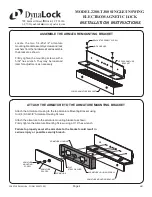
Using a 5/32” hex wrench, tempora rily
loosen the armature bracket assembly
screws roughly 1-1/2 turns to allow the
upper armature bracket to move in and out
freely (Ref. Figure “A”).
Close and latch the door. The mating
surfaces of the lock and armature should
fully contact each other. If necessary, slide
the armature in or out to ensure full contact
is made with the lock while still allowing the
door to properly close and latch. Move the
lock assembly up or down to achieve proper
vertical alignment.
When the desired adjustment is achieved,
slowly open the door taking care to maintain
the position of the armature. Firmly tighten
the armature bracket assembly screws,
making sure that the locking ribs on the
upper and lower bracket halves properly
mesh (Ref. Figure “A”).
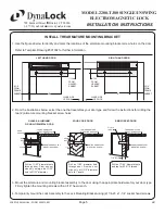
Dismount the lock assembly from the lock
mounting bracket and tighten the two slot
mounting screws. Using the bracket as a
template, drill and install the four remaining
bracket mounting screws. Mount the lock
and install the two aluminum anti-tamper
plugs using a soft faced mallet.
1.
2.
3.
4.
Figure “A”
ASSEMBLY
SCREW
UPPER ARMATURE BRACKET
LOWER
ARMAT URE
BRACKET
ARMATURE BRACKET
ADJUSTMENT RANGE
1/8"
1"
DOOR
LOCK ASSEMBLY
ARMATURE


