12
&DOLEUDWLRQ
A. Set the valve at the position where you want the
meter to read 0% (that is 4 mA). It may be necessary
to move the plug connector to change the direction of
current output to increasing for clockwise rotation or
vice versa.
B. On models 15XXX, loosen the two bottom set screws
on the coupling. Rotate the coupling and
potentiometer shaft to the position where the meter
reads 0% (4 mA). Tighten two set screws.
C. Turn valve to opposite position where meter should
UHDGP$8VHVPDOOVFUHZGULYHUWRDGMXVW
the blue rectangular potentiometer “span” until 100%
(20 mA) is on the meter. If it is not possible to reach
100%, refer to Troubleshooting instructions.
D. Return valve to original position at 0% (4 mA). Use
VPDOOVFUHZGULYHUWRDGMXVW³]HUR´WXUQLQJXQWLO
(4 mA) is read on meter. Repeat steps C and D until 4
and 20 mA read consistently on each end of stroke.
7URXEOHVKRRWLQJ
, ,IQRFXUUHQWÀRZVFKHFNSRODULW\RIFXUUHQWORRSSOXV
and minus screws on terminal strip). Also check loop
resistance for open line.
II. If full output current cannot be achieved by
DGMXVWPHQWYROWDJHDWWUDQVPLWWHUPD\EHWRRORZ,I
so, increase power supply voltage until a minimum of
15 V is registered or move voltage shunt to 12 VDC.
III. If current increases and decreases in the wrong
direction, move the plug connector from CW to CCW
or vice versa.
IV. Check specs to make sure you are in range of
DGMXVWPHQW6HHFKDUWRQSUHYLRXVSDJH
9 ,IWKH]HURDGMXVWPHQWGRHVQRWKDYHHQRXJKUDQJH
the zero must be mechanically realigned as follows:
6HWWKH³]HUR´¿QHP$DGMXVWPHQWWRWKHPLGGOHRI
its range. (Full multi-turn range is 25 revolutions; set
DWUHYROXWLRQV5HSHDWFDOLEUDWLRQVWHSV%&
and D.
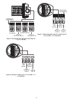
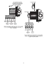
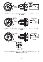
6HH 3DJHV
for wiring procedure, intrinsic safety
parameters, relevant warnings and schematics.
0$5.$1'75$160,77(5:,7++$57
®
&20081,&$7,21,167$//$7,21
Models 19XXX, 39XXX and 49XXX Rotary Position
Indicating Switches contain a 4-20 mA transmitter with
HART
®
communication and two Single Pole Double
Throw (SPDT) switches. Models 190XX, 390XX and
490XX contain a 4-20 mA transmitter with HART
®
communication only, no switches.
P$RXWSXWLVIXOO\DGMXVWDEOHIRUYDULRXV
rotations (zero and span) using pushbuttons or a
HART
®
communication master.
• 4-20 mA circuit is polarity insensitive and thermal
protected. Though the output terminals are labeled
DQGWKHWUDQVPLWWHUZLOOIXQFWLRQLIWKHWHUPLQDOV
are reversed.
• Clockwise
or
counterclockwise
rotation
corresponding
to increased current output can be selected by use of
zero and span pushbuttons or a HART
®
communication master.
,QVWDOODWLRQDQG$GMXVWPHQW
1. Attach the switch to the actuator or valve. Refer to
,QVWDOODWLRQDQG$GMXVWPHQWLQVWUXFWLRQV
p. 7 for Direct Drive Mark 1 and 4 Models
p. 8 for Lever Drive Mark 1 and 4 Models
2. Remove cover by unscrewing. Take care to keep
threads clean and free from damage.
3. On models 19XXX and 49XXX, the switches are set
at the factory when in the counterclockwise position
as shown. Switch #1 is open, and #2 is closed. When
FDPVDUHURWDWHGFORFNZLVHEHFRPHVFORVHG
DQGLVRSHQ7KHFDPVPD\EHDGMXVWHGWR
LQFUHDVHRUGHFUHDVHWKHURWDWLRQ)RUPRGHO
39XXX refer to pages 9 and 10 for Switch
$GMXVWPHQW3URFHGXUH
4. The potentiometer is positioned at the factory with the
resistance element approximately centered.
OPTIONAL
4-20 mA METER
24 VDC
POWER
SUPPLY
1
2
ZLUHFRQQHFWLRQV


