


11
Models 15XXX, 35XXX and 45XXX Rotary Position
Indicating Switches contain a 4-20 mA transmitter and
two Single Pole Double Throw (SPDT) switches. Models
150XX, 350XX and 450XX contain a 4-20 mA transmitter
only, no switches.
P$RXWSXWLVIXOO\DGMXVWDEOHIRUYDULRXVURWDWLRQV
(zero and span). See chart above for rotation ranges
using various potentiometers.
• 4-20 mA circuit is supply reversal protected and
thermal protected.
• Clockwise or counterclockwise rotation corresponding
WRLQFUHDVHGFXUUHQWRXWSXWFDQFRQYHQLHQWO\¿HOG
selected with plug connector.
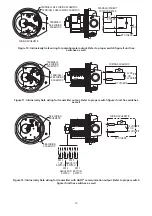
,QVWDOODWLRQDQG$GMXVWPHQW
1. Attach the switch to the actuator or valve. Refer to
,QVWDOODWLRQDQG$GMXVWPHQWLQVWUXFWLRQV
p. 7 for Direct Drive Mark 1 and 4 Models
p. 8 for Lever Drive Mark 1 and 4 Models
p. 9 for Mark 3 Models
2. Remove cover by unscrewing. Take care to keep
threads clean and free from damage.
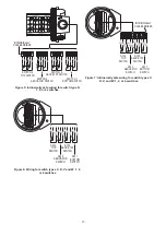
3. On models 15XXX and 45XXX, the switches are set
at the factory when in the counterclockwise position
as shown. Switch #1 is open, and #2 is closed. When
FDPVDUHURWDWHGFORFNZLVHEHFRPHVFORVHG
DQGLVRSHQ7KHFDPVPD\EHDGMXVWHGWR
LQFUHDVHRUGHFUHDVHWKHURWDWLRQ)RUPRGHO
35XXX refer to pages 9 and 10 for Switch
$GMXVWPHQW3URFHGXUH
4. The potentiometer is positioned at the factory with the
resistance element approximately centered.
Potentiometer
5HVLVWDQFHȍ
ȍ3HU
'HJUHH
RI5RWDWLRQ
5RWDWLRQ5DQJH
0DUNDQG 0DUN
Min
0D[
Min
0D[
1000
2000
2.9
5.8
1.5 turns
.75 turns
8.5 turns
4.3 turns
1 2 3
1
2
CLOCKWISE
ROTATION
0$5.$1':,7+75$160,77(5,167$//$7,21