T5L_ASIC Development Guide
- 26
-
www.dwin-global.com
DWIN Technology
Professional,
Creditable,
S
uccessful
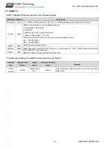
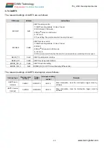
MUX_SEL
0xC9
Selection of peripheral reuse.
.7 1 = CAN interface leads to P 0.2 and P 0.3; 0 = CAN interface is not lead out, and it works
as an IO port.
.6 1 = UART2 interface leads to P 0.4 and P 0.5; 0 = UART2 interface is not lead out, and it works
as an IO port.
.5 1 = UART3 interface leads to P 0.6 and P 0.7; 0 = UART3 interface is not lead out, and it works
as an IO port.
.4-.2 Reserved;
.1 WDT control. 1=open; 0=close;
.0 WDT feed dog. 1=feed the dog one time(The WDT count becomes zero, and the watchdog's
overflowing time is 1 );
PORTDRV
0xF9
Driver capability configuration of IO port output mode, 0x00 = 4mA 0x01=8mA(recommended
values) 0x02=16mA 0x03=32mA
The relevant settings of IO port external interrupt are as follows.
Interrupt
type
Program entry
address
Trigger marker
Interrupt enabling
control
Remarks
EX0
interrupt
0x0003
IE0(TCON.1)
IEN0.0
IE0 is cleared automatically when interrupt response,
corresponding to P3.0.
IT0 (TCON.0) = 0 low level trigger interrupt, IT0 = 1 jump
down edge trigger interrupt.
EX1
interrupt
0x0013
IE1(TCON.3)
IEN0.2
IE1 is cleared automatically when interrupt response,
corresponding to P3.1.
IT1 (TCON.2) = low level trigger interrupt, IT1 = 1 jump
down edge trigger interrupt.

