


28
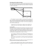
2B. Ceiling Mount Preparation
Once the throw distance has been calculated and the screen installed, the next step
in the installation is to locate the precise mounting position of the projector.
The ceiling mount bracket must be aligned to the middle of the screen and
located as close as possible to an electrical source AND a support beam. If the
projector is not located properly, it is not possible to compensate for any resulting
“keystone” distortion in the projected image.
IMPORTANT NOTES:
1. Before proceeding further with the installation, make certain that video signal/
control wiring and AC power have been run to the projector location. Keep in
mind that the connections to the projector are at the back of the unit.
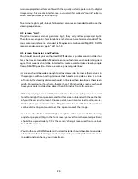
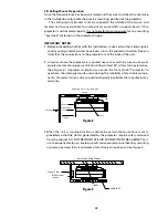
2. In rooms where the projector is mounted near a rear wall, be sure to allow ad-
equate clearance for proper ventilation. Allow at least 24” of rear-facing clearance.
(See Figure 2). Improper ventilation can cause the TransVision™ projector to
overheat, shortening lamp life and reducing the reliability of electronic compo-
nents. Projector failures due to overheating will invalidate the manufacturer’s
warranty.
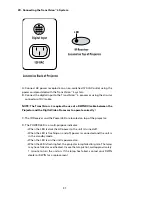
3. When the unit is mounted inside a cabinet, be certain that an exhaust vent is
provided so that the hot air generated by the projector may be safely removed
from the cabinet. DO NOT RECIRCULATE AIR FROM WITHIN THE CABINET. Fail-
ure to properly design an enclosure will cause projector overheating, resulting
in premature lamp failure and wear of electronic components. See Figure 3
Mounting Close to the Back Wall
CEILING
EXHAUST
DIGITAL INPUT
120 VAC
BACK WALL
24” MIN
INTAKE
Figure 2
Enclosed Ceiling Mount
ENCLOSURE
INTAKE
EXHAUST FANS
DIGITAL INPUT
120 VAC
Figure 3
Содержание DuoVision
Страница 1: ...DuoVision DuoVision 1 3 Printed in USA...
Страница 2: ......


