


CP-2202-361P/N User and Installation Guide
12
4.2.2
Wall Mounting
Wall mount methods covered in this section include:
Compact Pendant Mounting
Wall Box Mounting
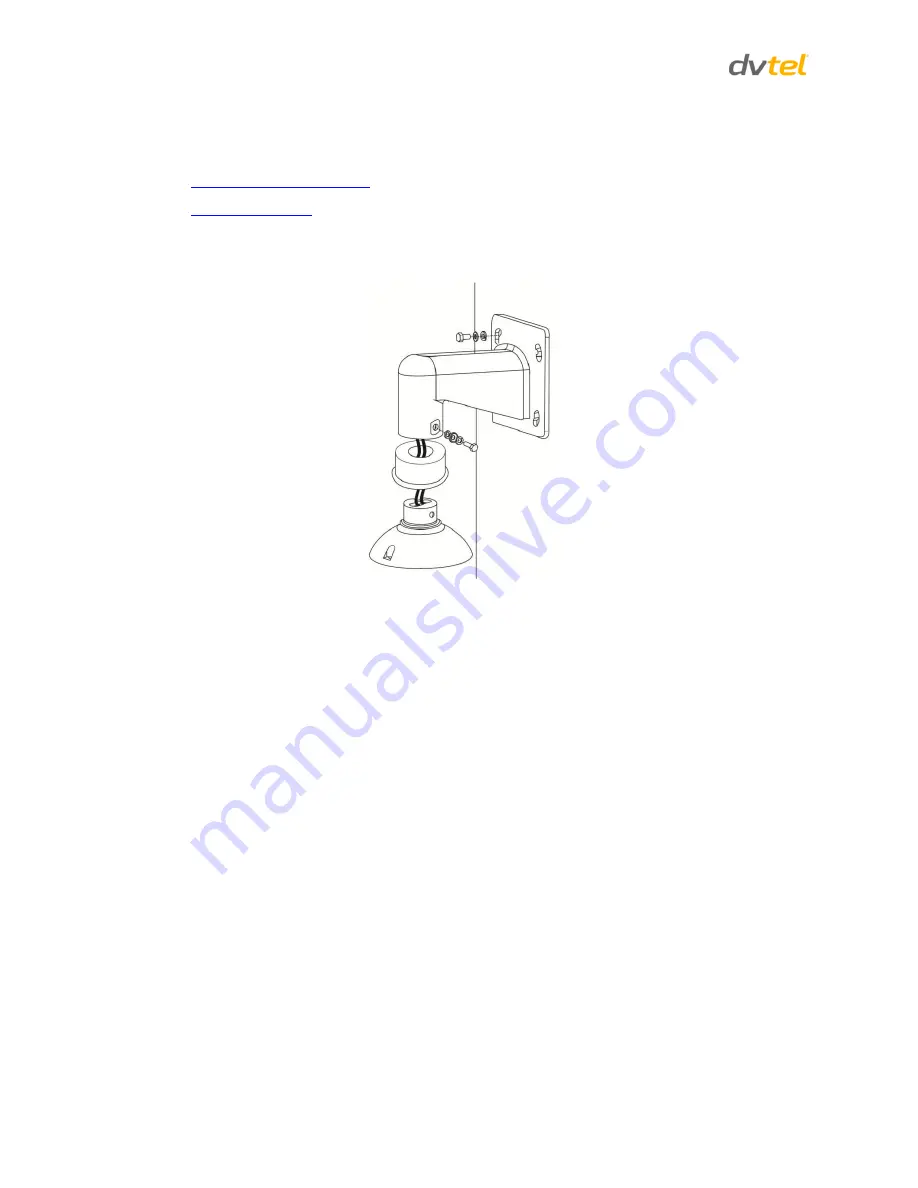
Compact Pendant Mount
4.2.2.1
Figure 12 - Compact Pendant Mount + Outdoor Mount Kit
Items Needed:
Outdoor Mount Kit (standard with outdoor cameras)
Compact Pendant Mounting package (DVTEL Camera Mounting Option available
separately)
Screws and screw anchors for fixing the Standard or Compact Pendant Mount (not
provided)
M5 Standard/Security Screw (supplied)
Standard or Compact Pendant Mounting Package Contents:
M8x12 screw x 1
Rubber washer-8 x 1
Spring washer-8 x 1
Pendant tube washer x 1
Waterproof rubber gasket x 1
Sponge x 2
Tools Required:
Drill
Phillips and flat-head screw drivers
Содержание ioimage CP-2202-361P/N
Страница 2: ......


