-5-
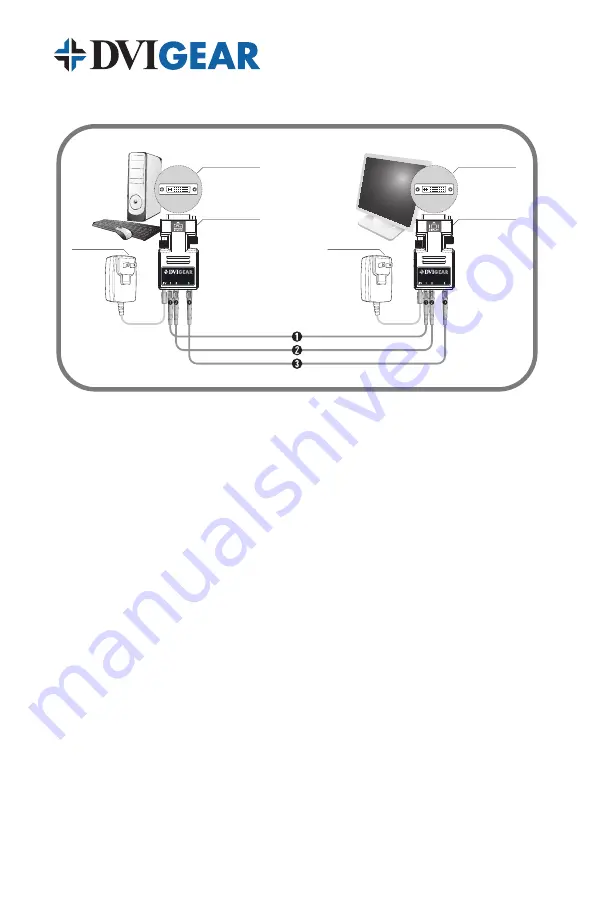
5. SYSTEM CONNECTIONS
DVI-7335-RX
Receiver
AC Power
Adapter
DVI-D Port
DVI-7335-TX
Transmitter
AC Power
Adapter
DVI-D Port
Typical System Diagram
5.1 DVI Interconnections
1. Connect each strand of the fiber optic cable to the corresponding
optical ports on the Transmitter and Receiver units which are marked
with the numbers 1, 2, and 3.
2. Connect the Transmitter unit (red label) to the source (e.g., PC, Blu-
Ray, receiver/switcher output).
3. Connect the Receiver unit (blue label) to the display (or receiver input,
switcher input).
4. Connect the supplied AC Power Adapters to the power input jacks on
the Transmitter and Receiver units and then to an AC power source.
5. Turn ON the Display, and then turn ON switchers and other distribution
equipment (if it exists). Finally, turn ON the source. Test the system to
ensure proper performance.
5.2 USB Interconnections
This unit is equipped with a USB 1.1 port that supports remote extension of
certain USB devices over the optical link. USB 1.1 operation is supported at
different distances based on the required data rates:
• USB 1.1 Low Speed: (Keyboard, Mouse): 300 /- 10%
• USB 1.1 Full Speed: (External Hard Drive, memory stick, USB Hub):
50 /- 10% (Use of a hub will reduce the maximum distance.)


