9
10
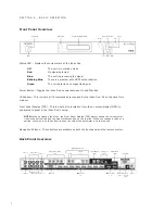
Audio Outputs
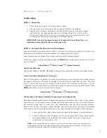
The iScan Duo has 3 types of audio outputs.
•
There are two discrete digital audio outputs, one coaxial and one optical.
Both are active at the same time, with the selected input audio stream.
•
The HDMI 1.3 audio only output for connection to an A/V Receiver.
•
The HDMI 1.3 audio and video outputs for connection to displays.
12V Trigger Outputs
There are two 12-volt trigger ports each capable of supplying 50mA.
•
12V Trigger 1 port
— Signal is ‘high’ when system is on
— Signal is ‘low’ when system is off
• 12V Trigger 2 port
— Signal is ‘high’ when HDMI Video Output 1 is selected
— Signal is ‘low’ when HDMI Video Output 2 is selected
RS232 Serial Connection
This connection is used as an interface to control the iScan Duo with an automation system.
Power Supply Input
The iScan Duo comes with a 12V@5A AC-to-DC converter power supply, which accepts 100-240 VAC
at 50/60Hz.
Mini USB Port
This connector is used for software updates using the supplied USB cable.
The most current software version is available at www.dvdo.com/duo.
IR Remote Control Jacks
The IR Remote input and output jacks are used with an IR repeater.
S E C T I O N 3 – I N I T I A L S E T U P
Initial Setup
STEP 1 - Power Up
1. Attach the power cord to the external power supply.
2. Plug the power cord into a wall outlet or power conditioner, if applicable.
3. Plug the small connector attached to the cable that comes out of the power supply
into the iScan. The iScan should power on and display ‘iScan Duo / DVDO’ on the
Front Panel Display (FPD). If this does not happen, check all connections and verify
that the power outlet does supply power with another device.
IMPORTANT: Use only the power supply that comes with your iScan Duo, or a
replacement procured directly from Simplay Labs.
STEP 2 - Connect the iScan Duo to the Display
Connect an iScan to a display with an HDMI or DVI input. The iScan Duo defaults to ‘Auto Select’
mode which automatically detects and outputs the display’s preferred format.
Some displays may not indicate their native resolution as the preferred format.
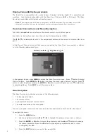
To manually change the Output Resolution, press the MENU button on the remote and use the on-screen
menu as shown.
Output Setup
_
Video Format
_
(Make Selection)
Useful Test Patterns:
Use the Test Patterns (ON/OFF,
t
and
u
) buttons on the remote for relevant test patterns below.
Frame Geometry (Adjusting for Overscan)
When this test pattern is displayed correctly, there should be a one-pixel wide white border around
the edge of the screen: otherwise, the display is overscanning the signal from the iScan Duo. This
is very common and is known for cutting off sports scores at the bottom of the screen. Use the
‘Underscan’ control to shrink the size of the output image so that you can see the white border. Press
MENU button and use the on-screen menu as shown.
Output Setup
_
Underscan
_
(Adjust Value)
Checkerboard (Verifying if Display’s Processing Can Be Bypassed)
When the checkerboard test pattern is displayed correctly, you should be able to see a 1-pixel checker-
board close-up. At the proper viewing distance the image should appear as an even gray. Otherwise,
the resulting image does not look like a fine checkerboard and may have irregular patterns.
When this is the case, the chosen output resolution may not be the native resolution of the display
or the display may scale all input signals even if the input resolution is already at native resolution.
1. Verify that the iScan Duo’s output resolution matches the display’s preferred format.
2. Check to make sure that the display is in the correct Aspect Ratio mode, which may be
causing the display to do additional unnecessary scaling. The correct mode may be
called ‘Native’, ‘Dot-by-Dot’ or ‘Full’.
NOTE: If this test pattern does not appear as it should, and you have chosen the native resolution
of the display, you may not be able to bypass the internal processing on the display. In these cases
select the closest output format to the display’s native resolution.


