Dürkopp Adler 755 B Скачать руководство пользователя страница 56

Operation

54

Operating Instructions 755 B, 756 B/F - 00.0 - 02/2021

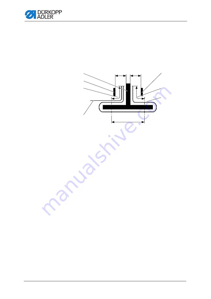
4.24 Flap and piping projection

Unhindered passage of the workpieces at the folder/pick-up folder requires 
that the maximum projections of piping, flap and material thickness (see di-
agram) not exceed the permissible limit. For the maximum allowable piping 
strip widths for the respective sewing equipment (E-No.), refer to the Equip-
ment Sheets of the 756.

Fig. 42: Flap and piping projection

(1)

- Folder

(2)

- Flap projection

(3)

- Flap

(4)

- Piping strip

(5)

- Piping projection max. 50 mm

(6)

- Guiding plate at the folder

NA: Seam projection
a, b: Material passage at the folder

a

b

NA


Содержание 755 B

Страница 1: ...755 B 756 B F Operating Instructions...

Страница 2: ...GmbH and protected by copyright Any reuse of these contents including extracts is prohibited without the prior written approval of D rkopp Adler GmbH Copyright D rkopp Adler GmbH 2021 IMPORTANT READ C...

Страница 3: ...e fabric sliding plate 32 4 12 Swiveling up the machine head 34 4 13 Swiveling down the machine head 36 4 14 Remaining thread monitor 38 4 15 Stacker control 39 4 16 Setting up double pipe single pipe...

Страница 4: ...tart sewing 79 4 28 2 Method B 80 4 28 3 Method F 89 5 Programming 97 6 Maintenance 291 6 1 Cleaning 292 6 2 Cleaning the incision device for piping ends 293 6 3 Replacing the incision knives for pipi...

Страница 5: ...Assembling the compressed air maintenance unit 321 7 9 2 Adjusting the operating pressure 322 7 10 Connection to the in house vacuum system 323 7 11 Connecting the vacuum compressor in the machine 32...

Страница 6: ...Table of Contents 4 Operating Instructions 755 B 756 B F 00 0 02 2021...

Страница 7: ...Specifically chapter Operation p 17 is important for the operators Specialists This group has the appropriate technical training for performing maintenance or repairing malfunctions Specifically the...

Страница 8: ...play control panel Important Special attention must be paid to this point when performing a step Information Additional information e g on alternative operating options Order Specifies the work to be...

Страница 9: ...le standards and regulations D rkopp Adler cannot be held liable for any damage resulting from Breakage and transport damages Failure to observe these instructions Improper use Unauthorized modificati...

Страница 10: ...About these instructions 8 Operating Instructions 755 B 756 B F 00 0 02 2021...

Страница 11: ...ine Only use original parts from the manufacturer Transport Use a lifting carriage or stacker to transport the machine Raise the machine max 20 mm and secure it to prevent it from slipping off Setup T...

Страница 12: ...ymbols used in warnings Warnings in the text are distinguished by color bars The color scheme is based on the severity of the danger Signal words indicate the severity of the danger Signal words Signa...

Страница 13: ...even fatal injury if ignored This is what a warning looks like for a hazard that could result in moderate or minor injury if the warning is ignored Puncture Crushing Environmental damage Symbol Type...

Страница 14: ...in environmental damage if ignored This is what a warning looks like for a hazard that could result in property damage if ignored CAUTION Type and source of danger Consequences of non compliance Measu...

Страница 15: ...ns 755 B 756 B F 00 0 02 2021 13 3 Machine description 3 1 Components of the machine Fig 1 Components of the machine class 756 F 1 Sewing light 2 Turning device 3 Tape unwinder 4 Pedals 5 Vacuum syste...

Страница 16: ...is intended for industrial use The machine may only be set up and operated in dry conditions on well maintained premises If the machine is operated on premises that are not dry and well maintained th...

Страница 17: ...755 B 756 B F 00 0 02 2021 15 3 3 Declaration of Conformity The machine complies with European regulations ensuring health safety and environmental protection as specified in the declaration of confor...

Страница 18: ...Machine description 16 Operating Instructions 755 B 756 B F 00 0 02 2021...

Страница 19: ...ore starting to work Inserting or changing the needle Threading the needle thread Threading or winding the hook thread Adjusting the thread tension 4 2 Switching on the machine Fig 2 Switching on the...

Страница 20: ...ght barriers are swiv eled out of the way to the left Fig 3 Swiveling the folder station out To swivel the folder station to the side 1 Press the handle 3 down to loosen the locking mechanism 2 Swivel...

Страница 21: ...vel down the light barriers 3 2 Swivel down the folder station 2 3 Lock the folder station 2 in place inside the locking mechanism 1 NOTICE Property damage may occur If the folder station is not fully...

Страница 22: ...le holders 1 until they reach the stop use only the correct needles p 351 CAUTION Risk of injury from sharp parts Punctures or cutting possible Only change needles with the main switch turned off When...

Страница 23: ...the needle thread Fig 6 Threading the needle thread 1 Left needle thread To thread the left needle thread 1 Swivel the folder station out p 18 2 Swivel the light barriers out to the left 3 Fit the thr...

Страница 24: ...e hole 9 in the mounting plate 11 Feed the needle thread through the holes of the thread regulator 15 12 Insert the needle thread through the upper hole in the thread lever 3 13 Feed the needle thread...

Страница 25: ...ght holes 22 in the mounting plate as shown above 6 Feed the needle thread through the guide 21 7 Guidetheneedlethreadcounterclockwisearoundtheadditionalthread tension 20 8 Guide the needle thread clo...

Страница 26: ...ad advancing device 5 16 Feed the needle thread through the needle thread monitor 6 17 Feed the needle thread through the guide 7 18 Feed the needle thread through the guide 8 19 Feed the needle threa...

Страница 27: ...ockwise into the front and rear reserve groove of the bobbin 4 7 Cut off the thread protruding at the thread pulling knife 6 8 Press the winder lever 3 into the bobbin 4 The winder starts up Informati...

Страница 28: ...ivel it to the left p 32 4 Lift the bobbin case upper section 1 The bobbin case retainer 2 will be lifted as well 5 Remove the bobbin case upper section 1 together with the empty bobbin 6 Remove the e...

Страница 29: ...thread behind the thread pulling knife 3 and tear it off 12 Replace the fabric sliding plate 13 Switch on the machine 14 Start a new sewing process 4 9 Thread tension Adjusting the hook thread tension...

Страница 30: ...g 4 and with the full bobbin into the bobbin case bottom section 5 Close the bobbin case retainer Fig 13 Adjusting the hook thread tension and the bobbin brake power 2 6 Turn the handwheel while keepi...

Страница 31: ...l increase the hook thread tension more than necessary if its pretension is excessive Pull off must be uniform and easy once the bobbin has been inserted and the hook thread 6 has been threaded throug...

Страница 32: ...etting at the control panel OP7000 under Program parameters Sewing head parameters Additional thread tension p 147 Important Together with the hook thread tension the needle thread tension influences...

Страница 33: ...B 756 B F 00 0 02 2021 31 4 10 Disconnecting the compressed air supply Fig 18 Disconnecting the compressed air supply To disconnect the compressed air supply 1 Pull the handle 1 on the compressed air...

Страница 34: ...the fabric sliding plate 1 CAUTION Risk of injury from moving parts Crushing possible Switch off the machine Do not slide the hood back and remove the fabric sliding plate back UNLESS the machine is s...

Страница 35: ...bric sliding plate 2 To disassemble the fabric sliding plate For machines with shims 1 Move the shims out of the throat plate area Press back the pedal for more than 1 second OR Press the Shim button...

Страница 36: ...carriage be in its rear position Fig 21 Swiveling up the machine head 1 To swivel up the machine head 1 Swing the folder station 3 out p 18 2 Disassemble the fabric sliding plate 2 3 Swivel the lever...

Страница 37: ...Operation Operating Instructions 755 B 756 B F 00 0 02 2021 35 Fig 22 Swiveling up the machine head 2 4 Lift and carefully swivel up the machine head The latch 4 locks into place as well 4 Latch...

Страница 38: ...d 1 Hold the machine head in place 2 Release the latch 1 3 Swivel down the machine head carefully WARNING Risk of injury from moving parts Crushing possible Switch off the machine Swivel up the machin...

Страница 39: ...ructions 755 B 756 B F 00 0 02 2021 37 Fig 24 Swiveling down the machine head 2 4 Insert the fabric sliding plate 3 5 Swivel the lever 2 down 6 Swivel down the folder station 4 2 Lever 3 Fabric slidin...

Страница 40: ...essage Error 3220 The pocket opening is safely finished with the remaining thread in the reserve groove of the bobbin hub The transport carriage stops at its rear end position It cannot be started aga...

Страница 41: ...of the reflected light barrier with a soft cloth once a day Workpiece is not conveyed out correctly If the workpiece is not moved out correctly the light beam between the reflected light barrier 2 and...

Страница 42: ...4 16 1 Changing the folder tools Fig 27 Changing the folder tools 1 To change the folder tools 1 Press Folder change position on the start screen 2 The spindles 1 move up 3 Switch off the machine NOT...

Страница 43: ...lder tools 2 4 Disconnect the hoses 2 of the pneumatic system from the pick up folder 3 Fig 29 Changing the folder tools 3 5 Flip the lever 4 while holding the pick up folder 3 in place 6 Pull the pic...

Страница 44: ...ew 8 on the folder 7 9 Pull the folder 7 down and out towards the side 10 Position the new folder and pull it down while pushing it in 11 Re tighten the screw 8 12 Carefully swivel back the method pla...

Страница 45: ...message 9014 warning of collisions the software setting for the folder tools is incorrect not sensible Check and if necessary correct the setting 4 16 2 Setting up double pipe Fig 32 Setting up double...

Страница 46: ...and set the transport clamps from double pipe to single pipe also requires a change of the folder tools at the OP7000 control panel Program parameters Process of transport clamp Transport clamp quick...

Страница 47: ...e station in and out CAUTION Risk of injury from sharp parts Cutting possible Swivel out the corner knife station only when the machine is switched off NOTICE Property damage may occur Unless swiveled...

Страница 48: ...755 B 756 B F 00 0 02 2021 Fig 34 Swiveling the corner knife station in and out 1 1 Corner knife station multi functional corner knife station automatic corner knife station slanted pocket automatic c...

Страница 49: ...e corner knife station out and back in 1 Switch off the machine 2 Slide the transport clamps to the rearmost position 3 Grasp the corner knife station 1 at the bottom and swivel it out to the left The...

Страница 50: ...ife station 1 Swivel out the corner knife station p 45 2 Loosen screws 2 and 4 3 Turn the knife holders 1 and 3 evenly 4 Tighten screws 2 and 4 5 Adjust the angle at the other pair of knives according...

Страница 51: ...usted by stepper motors You adjust the corner knife cuts at the OP7000 control panel Program parameters Corner knives p 153 Checking the cutting pattern Fig 38 Checking the cutting pattern Straight po...

Страница 52: ...mable marking lamp The programmable marking lamp 1 can be programmed in sewing direction The marking lamp lines up automatically with the corresponding positioning point front middle back The programm...

Страница 53: ...ble marking lamp The programmable marking lamp 1 can be programmed crosswise to the sewing direction for the sewing material that needs to be processed for example different trouser sizes The programm...

Страница 54: ...ead parameters Needle transport p 150 4 21 Stepper motor controlled transport clamp adjustment with material spreading Fig 41 Spreading the transport clamp The positions of the transport clamps relati...

Страница 55: ...ransport carriage is at its rear end position If not the display shows the message Reference run Warning 9000 2 Press the left pedal back The reference run starts The transport carriage moves to its r...

Страница 56: ...flap and material thickness see di agram not exceed the permissible limit For the maximum allowable piping strip widths for the respective sewing equipment E No refer to the Equip ment Sheets of the...

Страница 57: ...lder and guiding plates 4 25 1 Height of the pick up folder Fig 43 Height of the pick up folder The height of the pick up folder is adjusted using the OP7000 control panel Program parameters Guiding p...

Страница 58: ...1 Insert piping 2 Place the flap into the retracted and open turning device 3 Position the flap in the longitudinal direction relative to the jacket front part which must be aligned and fixed in place...

Страница 59: ...ck and transfers the flap to the open flap feeding device The flap is fed and sewn on Fig 47 Stripe correction 3 10 If a lateral shift from the pattern is discernible after sewing this shift can be of...

Страница 60: ...e bundle clamp The blow tube conveys the sewing material out of the stacking position Fig 48 Blow out device The setting for the blow out device is made using the OP7000 control panel Program paramete...

Страница 61: ...f the workpiece The setting for the roll off speed and the duty cycle is made using the OP7000 control panel Program parameters Stacker smoother blow off roll off p 179 Information The outfeed roller...

Страница 62: ...Press the button 2 into pin 3 while pulling pin 2 down at the same time The smoother 1 can be swiveled to the side to make the corner knife station accessible The setting for the smoother is made usin...

Страница 63: ...uctions on how to assemble the throw over stacker refer to the Setup chapter p 313 The setting for the throw over stacker is made using the OP7000 control panel Program parameters Stacker smoother blo...

Страница 64: ...out device and descend while being held by the bundle clamp Fig 54 Bundle clamp To operate the bundle clamp 1 Press the pedal 3 and hold it down The bundle clamp 2 opens 2 Insert the hind trousers par...

Страница 65: ...sitioning and working times are required Inserting the reinforcement strip Fig 55 Tape feeder and automatic cutter 1 To insert the reinforcement strip 1 Loosen the locking lever 6 and pull the washer...

Страница 66: ...abric sliding plate Information You can use knurled screws 7 to adjust the guide 9 individually to the width of the reinforcement strip 4 while knurled screws 8 let you make a lateral adjustment of th...

Страница 67: ...tting position and the cutting length is made using the OP7000 control panel Program parameters Adjust piping knife p 181 Fig 57 Position of the cutting areas The total length L of a piping incision c...

Страница 68: ...55 B 756 B F 00 0 02 2021 Important The incision device for piping ends must be cleaned regularly Depending on the material the knives may have to be replaced as well For a detailed description refer...

Страница 69: ...eters Program loading process Feeder on p 171 The feeding device is switched on 2 Press the right pedal forward and keep it there Both clamps 1 and 4 of feeding devices 2 and 3 open 3 Insert the flap...

Страница 70: ...ating Instructions 755 B 756 B F 00 0 02 2021 8 Press the left pedal forward The folding process is initiated The clamps of feeding devices 2 and 3 swivel out of the loading area and feed the flap or...

Страница 71: ...lining loop triangle Fig 60 Shaped guide lining loop triangle Adjusting the shaped guide To set the shaped guide 1 Loosen the screws 4 2 Set the shaped guide 3 in sewing direction towards the middle...

Страница 72: ...dal backwards The pocket bag 1 and the lining loop triangle 2 are clamped together Make sure the lining loop triangle 2 cannot slip 4 Release the right pedal 5 Press the left pedal forward The pocket...

Страница 73: ...2021 71 To use the zipper feeder 1 Cut the zipper 1 to the desired length 2 Apply custom positioning marks on the rest table 3 Push the zipper 1 into the guide bar 2 up to the positioning mark 4 If r...

Страница 74: ...62 Downholder and pocket bag clamp To operate the downholder and the pocket bag clamp 1 Push the pocket bag under the pocket bag clamp 2 and align 2 Position the hind trousers and align 3 Press the l...

Страница 75: ...band edge of the trousers in place thus allowing for optimal smoothing out of the fullness in the entire pocket area Fig 63 Waistband clamp To operate the waistband clamp 1 Push the pocket bag under t...

Страница 76: ...e p 171 4 27 14 Shims Fig 64 Shims The shims kit can be used for materials that are difficult to sew or transport such as lining viscose leather and rubber coated fabrics While being fed the sewing ma...

Страница 77: ...ystem is available the vacuum device is required for an accurate positioning of the workpieces Fig 65 Vacuum device To switch on the vacuum device 1 Switch on the switch 1 of the vacuum device 2 Go to...

Страница 78: ...t them in the Program parameters menu Fig 66 Pneumatic pocket bag clamp The setting for the mode of the pneumatic pocket bag clamp 1 is made using the OP7000 control panel Program parameters Program l...

Страница 79: ...r mechanical 1 To adjust the mechanical flap stopper 1 The mechanical adjustment of the flap stopper 1 is made at the top using the screw with scale 2 when the flap stopper 1 is swiveled out Fig 68 Fl...

Страница 80: ...driven The motor adjustable flap stopper can be used to sew a succession of pocket openings with flaps of different widths within a preset sewing sequence The motor driven flap stopper moves in accord...

Страница 81: ...equence is canceled The workpiece can be positioned again 3 Press the left pedal forward The sewing procedure is started The following is a brief description of the machines working methods Working me...

Страница 82: ...cket front part you will need to ensure a good match of stripes and checks even while preparing the sewing materials The alignment needed to match checks and stripes should always be made in the front...

Страница 83: ...left feeding device 10 closes 6 Press the right pedal back and keep it there The right feeding device 14 opens 7 Alignthepocketbag 15 withthepositioningmarkontheresttable 13 8 Release the right pedal...

Страница 84: ...15 swivel in 13 Press the left pedal forward The flap clamps close Feeding devices 10 and 14 open 14 Press the left pedal forward The sewing process starts Sewing left jacket front parts Fig 72 Sewin...

Страница 85: ...place The piping strip is incised and picked up by the pick up folder 18 The transport carriage moves to the loading position The transport clamps are lowered 12 Press the left pedal forward The pick...

Страница 86: ...0 02 2021 Information Depending on the selected pedal mode p 178 the loading process is completed either using inching operation or automatically With a press of the button on the start screen the pre...

Страница 87: ...the pocket opening 4 at the rear light spot 2 Position the hind trousers as close to the operator as possible This allows for the hind trousers once positioned to be safely smoothed out when the tran...

Страница 88: ...4 must amount to approx 30 mm OR 1 Position the left hind trousers 2 Attach positioning mark 9 The distance between positioning mark 9 and the light spot 2 must be 30 mm pocket length Fig 74 Sewing p...

Страница 89: ...according to positioning method a or positioning method b p 85 9 Press the left pedal forward Downholder 13 and waistband clamp 16 lower and clamp the hind trousers in their position 10 Smooth out th...

Страница 90: ...closes The sewing process starts Positioning correction To make positioning corrections 1 Press the left pedal back 1st pedal tap The flap clamp opens 2nd pedal tap The feeding device swivels back 3rd...

Страница 91: ...or right jacket front parts Fig 77 Sewing pocket openings with flap in jacket front parts 1 Important To achieve the best possible result when sewing the flap to the jacket front part you will need t...

Страница 92: ...eep it there The feeding device 12 for the pocket bag 11 opens 4 Alignthepocketbag 11 withthepositioningmarkontheresttable 10 5 Release the right pedal The feeding device 12 closes 6 Position the righ...

Страница 93: ...ping bar 11 Pull the front edge of the flap 15 up to the light spot 6 Make sure that the lateral edge of the flap 15 abuts on the flap stopper 17 12 Press the left pedal forward The flap clamping bar...

Страница 94: ...d piping strip the pick up folder 16 swivels into the vertical position and lowers the jacket front part The folding plates close 18 Press the left pedal forward The feeding device 14 with the flap 15...

Страница 95: ...lateral stop 3 Press the right pedal back and keep it there The feeding device 12 for the pocket bag 11 opens 4 Alignthepocketbag 11 withthepositioningmarkontheresttable 10 5 Release the right pedal...

Страница 96: ...amping bar 11 Pull the rear edge of the flap 15 up to the light spot 6 Make sure that the lateral edge of the flap 15 abuts on the flap stopper 17 12 Press the left pedal forward The flap clamping bar...

Страница 97: ...lap 15 swivels in The feeding device 12 holding the pocket bag 11 swivels in The flap clamps on the transport clamps close 19 Press the left pedal forward The sewing process starts Positioning correct...

Страница 98: ...0 02 2021 Information Depending on the selected pedal mode p 178 the loading process is completed either using inching operation or automatically With a press of the button on the start screen the pre...

Страница 99: ...Off p 188 Pocket bag clamp On Off p 188 Hook thread monitor On Off p 188 QONDAC On Off p 188 Start Bootloader Touchkalibrierung Hauptbildschirm Sequenzen Servicemen Programmparameter Taschenprogramme...

Страница 100: ...ogrammable guiding plates and folder height On Off p 189 1 25 Toolbox configuration p 195 Uninterrupted power supply On Off p 189 Select transport clamp type p 190 Shims On Off p 190 Adjustable transp...

Страница 101: ...2 2 11 Adjust and test needle transport p 233 2 11 1 Adjust needle transport p 232 2 12 Test pick up folder p 235 2 12 1 Folder adjustment p 236 Adjust and testing control panel p 227 2 13 Test middle...

Страница 102: ...281 5 0 Start screen 5 0 2 Overview of sequences p 117 5 0 2 1 Copy sequence p 123 5 0 2 0 Select source of sequence p 123 5 0 2 3 Select program p 116 p 117 Piece counter p 112 Activate automatic se...

Страница 103: ...amp X axis p 145 Adjust programmable marking lamp Y axis p 146 5 1 7 Sewing head parameters p 147 5 1 7 1 Adjust sewing speed p 147 5 1 7 2 Adjust soft start parameters p 148 Continuous or intermitten...

Страница 104: ...eam end right slanted pocket multi functional p 156 p 159 5 1 9 12 Corner knife angle correction seam begin left slanted pocket multi functional p 158 5 1 9 13 Corner knife angle correction seam begin...

Страница 105: ...0 Select pedal mode p 178 5 1 15 Stacker smoother blow off roll off p 179 Stacker On Off p 179 5 1 15 1 Select clamping time p 179 Smoother On Off p 179 Adjust smoother Start after corner cut p 179 5...

Страница 106: ...p 201 5 2 3 1 Time Thread clamp open p 201 5 2 3 2 Seam end mm till thread clamp opens p 201 5 2 3 3 mm with needle thread catcher open p 201 Adjust corner knife distance p 198 5 2 6 Adjust corner kni...

Страница 107: ...nitialize machine configuration p 276 Initialize global parameters p 276 Initialize all seam programs p 276 Initialize all sequences p 276 Initialize RAM p 276 10 0 Maintenance 10 3 Display software v...

Страница 108: ...with the user interface in symbolic representation Fig 82 Control panel OP7000 Switching on the machine After the machine has been switched on the control and the OP7000 control panel will start up Ne...

Страница 109: ...touch pad The start screen is divided into the areas below 1 Pocket programs in sequence 2 Automatic seam sequence 3 Overview of seam sequences 4 Piece counter 5 Seam pattern 6 Positioning points 7 Qu...

Страница 110: ...highlighted with a red circle Display of selected seam pattern the display changes with the setting of the pocket program with without flap Positioning point seam begin Positioning point seam center P...

Страница 111: ...is highlighted with a red circle and dots on the side Help is activated permanently A Help text is displayed for every button you press Press the Help button again to deactivate this mode Help is dea...

Страница 112: ...ering values using the numeric keypad To enter values using the numeric keypad 1 Enter the desired value 2 Confirm with OK To enter a negative value on the numeric keypad 1 Enter the desired value 2 P...

Страница 113: ...itor To enter text using the text editor 1 Use the keyboard to enter text 2 If you need to correct or delete text press the button and delete the letters or numbers you wish to delete OR 3 In the text...

Страница 114: ...e effect Fig 86 Entering values using the numeric keypad 2 Piece counter Reset piece counter To reset the piece counter 1 Press the button briefly The piece counter is reset to 0 Adjusting initial pie...

Страница 115: ...nce button The display switches to Overview of sequences Fig 87 Creating or changing a seam sequence 1 1 Selected seam sequence 2 Display of pocket programs in the sequence 3 Scroll down seam sequence...

Страница 116: ...am sequence is highlighted with a bold frame and the color orange 1 4 Press the button The display switches to Create sequence via drag drop Fig 88 Creating or changing a seam sequence 2 Call up addit...

Страница 117: ...rogram is positioned via Drag and Drop the left half of the display will show the seam pattern of the pocket program The pocket programs will be stored in the seam sequence in the order in which they...

Страница 118: ...nce 2 Use Drag and Drop to drag the desired pocket program from the tem plate to an available pocket program slot The display switches to Select program Fig 89 Selecting pocket programs from the seam...

Страница 119: ...program slot 1 To create a seam sequence 1 Use Drag and Drop to drag any pocket programs you do not need from the sequence to be created 10 to the trash OR tap on the trash to delete all pocket progr...

Страница 120: ...n other seam sequences The currently selected pocket program is highlighted in orange 3 Select the desired pocket program You can select no more pocket programs than there are available pocket program...

Страница 121: ...Changing the seam sequence template 1 To change the seam sequence template 1 Press the S01 button The display switches to Select source of sequence Fig 93 Changing the seam sequence template 2 The de...

Страница 122: ...quence The display returns to Create sequence via drag drop Information Cancel the selection by pressing the same sequence again Fig 94 Changing the seam sequence template 3 4 Use Drag and Drop to dra...

Страница 123: ...am sequence template 1 to an available pocket program slot OR Press the button to selectthe desired pocketprogram from the list 6 Press the button to save the setting and return to the previous level...

Страница 124: ...equence 1 To enter a name for a seam sequence 1 Press the button S02 S20 depending on which seam sequence you have selected The display switches to a keypad Fig 97 Naming a seam sequence 2 2 Enter the...

Страница 125: ...sequences Fig 98 Copying a seam sequence 1 2 Select the seam sequence you wish to copy from the list To scroll up and down the list of sequences press the buttons and 3 Press the desired seam sequenc...

Страница 126: ...d with a bold frame and the color orange 5 Select the seam sequence you wish to overwrite from the list To scroll up and down the list of sequences press the buttons and OR drag the bar up or down Inf...

Страница 127: ...The display returns to Overview of sequences Activating a pocket program from the seam sequence You can activate a single pocket program stored in the seam sequence if you wish to sew a specific pock...

Страница 128: ...ways sews using the selected pocket program Activating the automatic seam sequence If the automatic seam sequence is activated the machine will automatically sew the next pocket program in the sequenc...

Страница 129: ...ailable or grayed out it must be set up in the Machine configuration menu p 187 Otherwise the option will be unavail able in this class To configure pocket programs 1 Press the Program parameters butt...

Страница 130: ...knife parameters p 151 Corner knife p 153 Automatic tape feeder optional p 162 Transport clamp p 163 Process of transport clamp p 166 Program loading process p 171 Stacker smoother blow off roll off...

Страница 131: ...ypad to set the desired pocket program 1 200 2 Confirm with OK The display switches to the selected pocket program You can configure the selected pocket program as described below Important When you r...

Страница 132: ...name of the pocket program 2 Confirm with OK The display switches to the selected pocket program Copying a pocket program The display switches to Copy pocket program Fig 104 Copying a pocket program...

Страница 133: ...ination program will be overwritten during the copying process If necessary you will have to make additional adjustments in the software If selecting a destination that is already used in another sequ...

Страница 134: ...s 755 B 756 B F 00 0 02 2021 Creating a seam program The display switches to Create seam program Fig 106 Creating a seam program Press a button to either open another submenu or enter the desired valu...

Страница 135: ...mm Pocket shape seam begin straight slanted slanted Adjust pocket shape seam begin 1 13 mm Securement seam beginning left right needle Stitch condensing OR Single backtack OR Double backtack Flap shap...

Страница 136: ...beginning p 138 100 mm 100 mm Adjust correction value of positioning point in the middle of the seam p 138 100 mm 100 mm Adjust correction value of positioning point at seam end p 138 100 mm 100 mm Th...

Страница 137: ...lue using the numeric keypad 3 Confirm with OK Symbols Meaning Select stitch condensing Adjust stitch length for stitch condensing at seam beginning 0 5 4 5 mm Adjust number of stitches for stitch con...

Страница 138: ...edle is adopted Adjusting securement seam beginning right needle Information The settings in sub item Securement seam beginning right needle are adopted automatically from the settings for the Securem...

Страница 139: ...ed automatically from the settings for the Securement seam end left needle p 136 Symbols Meaning Select stitch condensing Adjust stitch length for stitch condensing at seam end 0 5 4 5 mm Adjust numbe...

Страница 140: ...hes to Adjust positioning point correction value Fig 109 Adjusting correction values of the positioning points Information The arrows in the left half of the display indicate the correction direction...

Страница 141: ...fixed seam length manual working method Adjust sewing length Not available unless Activate sewing length has been selected 20 mm 180 mm 200 mm 220 mm 240 mm depending on the sewing length set Activat...

Страница 142: ...set the display will switch from the seam program to the start screen The display shows the flap and the flap scan and corner knife correction can be set via the quick access menu Fig 111 Activating...

Страница 143: ...rrection light barrier Fig 112 Correction light barrier To make a correction to the light barrier 1 Press the desired button 2 Enter the desired value using the numeric keypad 3 Confirm with OK Symbol...

Страница 144: ...end The display switches to Correction light barrier seam begin end Fig 113 Adjusting correction light barrier seam begin end Information The arrows in the left half of the display indicate the correc...

Страница 145: ...143 Marking lamps 1 16 The display switches to Marking lamps 1 16 Fig 114 Marking lamps 1 16 Symbols Meaning Activate marking lamps 1 16 p 144 Programmable marking lamps in sewing direction p 145 Prog...

Страница 146: ...00 0 02 2021 Activating marking lamps 1 16 Fig 115 Activate marking lamps 1 16 To activate the marking lamps 1 Press the button of the desired marking lamp The marking lamp is de activated Symbols Mea...

Страница 147: ...e button or The desired marking lamp moves to the corresponding position 2 Press the button or 3 Enter the desired correction value using the numeric keypad 4 Confirm with OK Symbols Meaning Programma...

Страница 148: ...Fig 117 Programmable marking lamps Y axis To program the programmable marking lamps for the Y axis 1 Enter the desired correction value using the numeric keypad 2 Confirm with OK Symbols Meaning Progr...

Страница 149: ...st sewing speed 100 RPM 3200 RPM Adjust soft start parameters p 148 Soft start On Off Soft start speed Number of stitches soft start Number of stitches needle thread clamp open Adjust continuous trans...

Страница 150: ...parameters The display switches to Soft start parameters Fig 119 Adjusting soft start parameters To edit the soft start parameters 1 Press the desired button 2 Enter the desired value using the numeri...

Страница 151: ...lay switches to Seam securement Fig 120 Adjusting seam securement To adjust the speed of the seam securement 1 Press the desired button 2 Enter the desired value using the numeric keypad 3 Confirm wit...

Страница 152: ...55 B 756 B F 00 0 02 2021 Needle transport Fig 121 Needle transport Symbols Meaning Needle transport On Off Adjust needle transport at seam beginning 0 100 Adjust needle transport in main seam 0 100 A...

Страница 153: ...rm with OK Symbols Meaning Middle knife On Off Adjust middle knife correction seam begin p 152 9 9 mm 9 9 mm Adjust middle knife correction seam end p 152 9 9 mm 9 9 mm Automatic speed adjustment On O...

Страница 154: ...e display switches to Adjust middle knife correction seam begin seam end Fig 123 Adjusting middle knife correction seam begin seam end Information The arrows in the left half of the display indicate t...

Страница 155: ...traight pocket Fig 124 Corner knife Straight pocket To adjust the corner knife 1 Press the desired button 2 Enter the desired value using the numeric keypad 3 Confirm with OK Symbols Meaning Corner kn...

Страница 156: ...nife correction seam begin seam end Fig 125 Adjusting corner knife correction seam begin seam end Information The arrows in the left half of the display indicate the correction direction Seam beginnin...

Страница 157: ...n in the submenu Corner knife device in the Machine configuration p 187 After making the conversion in the Machine configuration you must restart the machine The display switches to Corner knife Slant...

Страница 158: ...nter the desired value using the numeric keypad 3 Confirm with OK Adjusting corner knife correction seam begin seam end Fig 127 Adjusting corner knife correction seam begin seam end Correction seam en...

Страница 159: ...ructions 755 B 756 B F 00 0 02 2021 157 Information The arrows in the left half of the display indicate the correction direction Seam beginning Correction outward Correction inward Seam end Correction...

Страница 160: ...ce in the Machine configuration p 187 After making the conversion in the Machine configuration you must restart the machine The display switches to Corner knife Slanted pocket Fig 128 Corner knife sla...

Страница 161: ...ng corner knife correction seam begin seam end Fig 129 Adjusting corner knife correction seam begin seam end Corner knife seam end left On Off Correct corner knife angle seam end left p 160 9 9 9 9 Co...

Страница 162: ...e arrows in the left half of the display indicate the correction direction Seam beginning Correction outward Correction inward Seam end Correction inward Correction outward Correcting corner knife ang...

Страница 163: ...02 2021 161 Information The arrows in the left half of the display indicate the correction direction Seam beginning Correction inward smaller angle Correction outward greater angle Seam end Correction...

Страница 164: ...eeder The display switches to Automatic tape feeder Fig 131 Automatic tape feeder Symbols Meaning Automatic tape feeder On Off Adjust length of tape at seam begin 0 99 mm Adjust length of tape at seam...

Страница 165: ...the desired values directly using the numeric keypad Symbols Meaning Adjust return speed 10 100 Adjust insertion speed 10 100 Adjust softstart for insertion speed Insertion speed fast Insertion speed...

Страница 166: ...rn of transport clamp Fig 133 Adjusting return of transport clamp Symbols Meaning Activate without transport Adjust transport up to stacking position 1 mm 100 mm Activate transport up to loading posit...

Страница 167: ...ting position of transport clamp The display switches to Waiting position of transport clamp Fig 134 Adjusting waiting position of transport clamp To adjust the waiting position of the transport clamp...

Страница 168: ...ing Transport clamp quick adjustment p 167 only active if the transport clamp adjustment in the machine configuration is set to manual Select process of transport clamp p 168 Select piping type p 169...

Страница 169: ...t The display switches to Quick clamp adjustment Fig 136 Selecting transport clamp quick adjustment To select the transport clamp quick adjustment Press the desired button Symbols Meaning Left in righ...

Страница 170: ...clamp 1 Press the desired button Symbols Meaning Lower both transport clamps together Lower left transport clamp first Lower right transport clamp first Depressurize both transport clamps together Lo...

Страница 171: ...right inside double pipe 9 9 mm 9 9 mm Left out right in single pipe left Correction clamp left outside single pipe left 9 9 mm 9 9 mm Correction clamp right inside single pipe left 9 9 mm 9 9 mm Left...

Страница 172: ...d transport clamp Fig 139 Spreading the transport clamp To spread the transport clamp 1 Press the desired button 2 Enter the desired value using the numeric keypad 3 Confirm with OK Symbols Meaning Co...

Страница 173: ...utton to either open another submenu or enter the desired values directly using the numeric keypad Symbols Meaning Select flap clamps Both flap clamps close together Left flap clamp closes first Right...

Страница 174: ...ng device On Off Feeding device mode Swivel out without lowering Standard mode for fast reloading of all additional parts Feeding device remains swiveled in without lowering e g for zipper Feeding dev...

Страница 175: ...st be activated in the ma chine configuration p 187 The display switches to Select downholder mode Fig 141 Selecting downholder mode Symbols Meaning 1 Downholder waistband clamp 2 Vacuum 1 Downholder...

Страница 176: ...the desired button Information The numbering of the buttons downholder vacuum and waist band clamp in the lower half of the display changes with the selected setting 1 Waistband clamp 2 Downholder 3...

Страница 177: ...late 3 Blowing ON at flap clamp 1 Lower folder 2 Blowing ON at flap clamp blowing ON at folding plate for 10 mm seam path Not active in 755 A and 756 A 1 Lower pickup folder blowing ON at flap clamp f...

Страница 178: ...s 755 B 756 B F 00 0 02 2021 To select blowing mode 1 Press the desired button Information The numbering of the buttons folding plate flap clamp and low er pickup folder in the lower half of the displ...

Страница 179: ...osi tion Blow pocket bag and or piping briefly Blow piping already while folder is lowering Mode 4 B F Blow tube in folding plate Lower folder Flap clamps closed Blow tube in flap clamps Flap clamps c...

Страница 180: ...is completed without stop Push pedal after each step Vacuum downholder and transport clamp are each triggered with one step during the loading process the sewing process starts after the flap clamps h...

Страница 181: ...grip stacker signal only with active pincer stacker 0 ms 2000 ms Select earlier clamping time only with active throw over stacker 0 ms 1000 ms Smoother On Off only with active smoother Adjust duration...

Страница 182: ...ut device and the outfeed roller 1 Press the desired button 2 Enter the desired value using the numeric keypad 3 Confirm with OK Adjust roll off time 0 ms 3000 ms Adjust roll off speed 1 15 Adjust tim...

Страница 183: ...desired button 2 Enter the desired value using the numeric keypad 3 Confirm with OK Symbols Meaning Piping knife On Off Adjust cutting position at seam beginning Value range 0 150 mm Adjust cutting l...

Страница 184: ...lder Fig 146 Adjusting guiding plates and folder Symbols Meaning Guiding plates and folder left thin middle thick Adjust offset value left Value range 2 2 mm Adjust offset value right Value range 2 2...

Страница 185: ...he folder 1 Press the desired button 2 Enter the desired value using the numeric keypad 3 Confirm with OK Lift guiding plates right lift up to seam beginning for extra thick material Value range 0 6 m...

Страница 186: ...ting Instructions 755 B 756 B F 00 0 02 2021 Pattern matching The display switches to Pattern matching Fig 147 Pattern matching Symbols Meaning Patterned or plain material Flap projection 3 0 mm 3 0 m...

Страница 187: ...display switches to Flap stopper Fig 148 Flap stopper Symbols Meaning The flap stopper automatically rises after the flap clamp is closed The flap stopper can be alternately raised and lowered using...

Страница 188: ...tton The display switches to the Service menu Fig 149 Service menu Button Meaning Configure machine settings p 187 Adjust basic machine parameters p 197 Test and set individual machine functions p 204...

Страница 189: ...u is protected with a password You use this menu to set basic machine functions The password is 25483 The display switches to Machine config Fig 150 Machine configuration Press a button to either open...

Страница 190: ...hook thread monitor does not appear in the Global parameters p 197 If the hook thread monitor is deactivated the maximum bobbin thread counter appears in the Global parameters and must be configured m...

Страница 191: ...55 B and 756 B Transport clamp adjustment manual automatic Corner knife device without corner knife device straight pocket manual corner knife device straight pocket automatic corner knife device stra...

Страница 192: ...lay switches to Select machine class Fig 151 Selecting the machine class To select the machine class and the matching seam length 1 Select the desired class 1 2 Select the desired working method 2 Sel...

Страница 193: ...hs depend on the equipment When you switch to another class tools that are not available for the se lected class may be removed from the toolbox on the start screen Selecting needle distance The displ...

Страница 194: ...r The display switches to Feeder and programmable flap stopper Fig 153 Feeder and programmable flap stopper To adjust the feeder 1 Press the desired button Symbol Meaning automatic flap feeder deactiv...

Страница 195: ...rrier scan To adjust the light barrier scan 1 Press the desired button The settings for the left and the right light barrier can be configured separately Information The available options vary with th...

Страница 196: ...play switches to Pedal operation Fig 155 Pedal operation To adjust the pedal operation Press the desired button Symbol Meaning Operation with 1 pedal Operation with 2 pedals 1st pedal right function p...

Страница 197: ...een selected for this position yet Depending on the class and method the display will only show the tools available and configured for that class and method To configure the toolbox 1 Press on a blank...

Страница 198: ...configuration 2 Information You can use the button to remove a previously selected tool from the toolbox again Tools already in use are grayed out 2 To navigate up and down the list use the arrow but...

Страница 199: ...rograms The password is 25483 Information If an option is not available or grayed out it must be set up in the Machine configuration menu p 187 Otherwise the option will be unavailable in this class T...

Страница 200: ...ust corner knife distance reference pocket length 20 240 mm Adjust corner knife Adjust cutting duration 0 ms 1000 ms set maximum hook thread counter only visible in global parameters if hook thread mo...

Страница 201: ...sport clamp adjustment is set to AUTOMATIC in the machine configuration without bypass bypass left bypass right bypass left and right Adjust machine process speed slow middle fast Adjust password prot...

Страница 202: ...ired value using the numeric keypad 3 Confirm with OK Symbol Meaning Lower transport clamp automatically On Off Adjust delayed lifting of transport clamp 0 ms 1000 ms Adjust transport clamp speed to w...

Страница 203: ...ad clamp catcher tension To adjust the needle thread clamp the needle thread catcher and the needle thread tension 1 Press the desired button 2 Enter the desired value using the numeric keypad 3 Confi...

Страница 204: ...der height To adjust the guiding plates and the folder height 1 Press the desired button 2 Enter the desired value using the numeric keypad 3 Confirm with OK Symbol Meaning Default Guiding Plate thin...

Страница 205: ...passwords for the levels listed below on or off The display switches to Adjust password protection Fig 162 Adjusting password protection To adjust password protection 1 Press the button in front of t...

Страница 206: ...blies and eliminate errors The password is 25483 The display switches to Machine test The display varies with the machine configuration p 187 Fig 163 Machine test Symbol Description USB logger p 206 A...

Страница 207: ...p 227 Test piping knife p 231 Adjust and test needle transport p 233 Test pick up folder p 235 Test and set middle knife p 237 Adjust and test programmable marking lamps p 240 only if the programmable...

Страница 208: ...er 2 Load the Log txt file onto a USB key 3 Plug the USB key with the Log txt file into the USB port on the control panel 4 Confirm with OK OP7000 logging automatically writes all status messages of t...

Страница 209: ...15 If the value is above the minimum value of 8 the display shows an arrow between reflecting head and hook thread bobbin A signal tone will sound at the same time Important If the light barrier setti...

Страница 210: ...ng the outfeed roller The display switches to Test roll off device Fig 166 Testing the outfeed roller To test the outfeed roller 1 Press the desired button 2 Enter the desired value using the numeric...

Страница 211: ...the Service Instructions for instructions on how to align the light barriers with the help of templates For information on how to connect the light barriers see the wiring diagram included in the Appe...

Страница 212: ...the items that can be set in the Align light barriers menu item 2 Press the desired button Symbol Meaning Reference Lift pick up folder lower pick up folder depressurized Transport clamp quick adjustm...

Страница 213: ...station 1 Press the button Reference run is carried out The following table lists the items that can be set in the Test corner knife menu item CAUTION Risk of injury from moving parts Crushing Do NOT...

Страница 214: ...0 30 0 Adjust knife block seam begin left 13mm 13 mm Adjust angle seam begin right p 213 only for configuration multi functional corner knife station 0 0 30 0 Corner knife seam begin right On Off Cor...

Страница 215: ...eam end Fig 169 Adjusting corner knife angle seam begin seam end Information The arrows in the left half of the display indicate the correction direction Seam beginning Correction inward smaller angle...

Страница 216: ...corner knife at seam begin zero 13 mm 13 mm Offset corner knife at seam begin left zero p 215 only for configuration multi functional corner knife station 0 30 Correction value corner knife seam begi...

Страница 217: ...justing offset angle seam begin seam end Fig 171 Adjusting offset angle seam begin seam end Offset corner knife at seam end left zero p 215 only for configuration multi functional corner knife station...

Страница 218: ...0 0 02 2021 Information The arrows in the left half of the display indicate the correction direction Seam beginning Correction inward smaller angle Correction outward greater angle Seam end Correction...

Страница 219: ...tor Fig 172 Testing the sewing motor NOTICE Property damage may occur Jamming of the machine Unthread the needle thread before starting the sewing motor Symbols Meaning Adjust sewing motor p 218 Adjus...

Страница 220: ...d item is displayed Adjusting the sewing motor The display switches to Adjust sewing motor Fig 173 Adjusting the sewing motor To adjust the sewing motor 1 Press the desired button 2 Enter the desired...

Страница 221: ...perform a machine workflow test 1 Press the desired button The user interface for setting the desired item is displayed Symbols Meaning Exit current machine test return to start screen Loading process...

Страница 222: ...ing path Information To monitor the transport path of the sewing material reduce the insertion speed prior to the loading process test p 163 To perform a loading process test 1 Press the Loading proce...

Страница 223: ...by step Fig 176 Test step by step To carry out a step by step test 1 Press the Test step by step button 2 Press the pedal after every single work step The step by step test allows you to test the mach...

Страница 224: ...he display switches to Cycle time Fig 177 Cycle time To test the cycle time 1 Sew The display shows the time in ms The cycle time allows you to optimize the machine settings 2 To exit the test access...

Страница 225: ...der Fig 178 Testing turning device without folder To test the turning device without folder 1 Press the Test turning device w o folder button 2 Press the pedal after every single work step The step by...

Страница 226: ...older Fig 179 Testing the turning device with folder To test the turning device with folder 1 Press the Test turning device w folder button 2 Press the pedal after every single work step The step by s...

Страница 227: ...r motor To test the stepper motor 1 Press the button Reference run is carried out CAUTION Risk of injury from moving parts Crushing possible When you advance the transport clamp the transport clamp wi...

Страница 228: ...f there is a difference between the Encoder and Position values you can reset the values by carrying out a reference run Symbol Meaning Adjust clamp speed 10 100 Adjust stepper motor pos 1 0 517 5 mm...

Страница 229: ...t control panel Fig 181 Adjusting and testing control panel To adjust and test the control panel 1 Press the desired button The user interface for setting the desired item is displayed Symbol Meaning...

Страница 230: ...htness and contrast The display switches to Adjust brightness and contrast Fig 182 Adjust brightness and contrast To adjust the brightness of the display 1 Move the controller Increase brightness Slid...

Страница 231: ...libration is carried out The display returns to Adjust and test control panel OR 1 Press Cancel Touch calibration is canceled The display returns to Adjust and test control panel Information Another o...

Страница 232: ...Programming 230 Operating Instructions 755 B 756 B F 00 0 02 2021 Touch test The display switches to Touch test Fig 184 Touch test The Touch test menu item allows you to draw on the touch screen...

Страница 233: ...ng knife Fig 185 Testing piping knife Symbol Meaning Adjust piping knife p 232 Test cutting process 0 180 mm Test cutting process both knives Piping knife seam beginning On Off Piping knife seam end O...

Страница 234: ...utton Adjusting piping knife The display switches to Adjust piping knife offset Fig 186 Adjusting piping knife To adjust the piping knife 1 Press the desired button 2 Enter the desired value using the...

Страница 235: ...Fig 187 Testing needle transport To test the needle transport 1 Press the button Reference run is carried out 2 Press the desired button Symbol Meaning Adjust needle transport p 232 Reference Stepper...

Страница 236: ...sting needle transport To adjust the needle transport 1 Press the button 2 Enter the desired correction value using the numeric keypad The needle bar moves to the specified position 3 Keep correcting...

Страница 237: ...o Test pick up folder Fig 189 Testing pick up folder To test the pick up folder 1 Press the button Reference run is carried out 2 Press the desired button Symbol Meaning Folder adjustment p 236 Pick u...

Страница 238: ...0 0 02 2021 Folder adjustment The display switches to Folder adjustment Fig 190 Folder adjustment To adjust the folder 1 Press the button 2 Enter the desired value using the numeric keypad 3 Confirm w...

Страница 239: ...91 Testing middle knife To test the middle knife 1 Press the button Reference run is carried out 2 Press the desired button Symbol Meaning Adjust middle knife p 238 Middle knife On Off Stepper motor O...

Страница 240: ...desired value using the numeric keypad 3 Confirm with OK Symbol Meaning Adjust correction lower position cutting position 10 mm 10 mm Adjust height of stroke 1 mm 7 mm Adjust correction upper position...

Страница 241: ...roke Fig 193 Middle knife correction upper lower position height of stroke Information The arrows in the left half of the display indicate the correction direction Correction upward middle knife less...

Страница 242: ...ing lamps test Fig 194 Testing programmable marking lamps Information If only one of the programmable marking lamps is active the menu switch es directly to the corresponding submenu Symbol Meaning Te...

Страница 243: ...mmable marking lamps To test the programmable marking lamps 1 Press the button Reference run is carried out 2 Press the button or The desired positioning point has been selected Symbol Meaning Adjust...

Страница 244: ...lengthwise The display switches to Adjust programmable marking lamps Fig 196 Adjusting programmable marking lamps lengthwise Symbol Meaning Select front positioning point Select central positioning p...

Страница 245: ...ting programmable marking lamps To test the programmable marking lamps 1 Press the button Reference run is carried out 2 Press the button or The desired positioning point has been selected 3 Press the...

Страница 246: ...display switches to Adjust programmable marking lamps Fig 198 Adjusting programmable marking lamps crosswise Symbol Meaning Adjust programmable marking lamp position 1 Value range 100 100 Adjust prog...

Страница 247: ...on Reference run is carried out 2 Press the desired button Symbol Meaning Adjust transport clamp p 246 also used for direct troubleshooting in case of error codes 2501 2505 2601 and 2605 If error code...

Страница 248: ...may occur Damage to the transport clamp from incorrect setting Jamming of the stepper motor Symbol Meaning Adjust correction value left clamp 10 0 mm 10 0 mm Adjust distance outer position left clamp...

Страница 249: ...tion of the clamps varies with the transport clamp quick adjustment p 169 Adjust correction value right clamp 10 0 mm 10 0 mm Adjust distance inner position right clamp double pipe 0 0 mm 40 0 mm Adju...

Страница 250: ...play switches to Test guiding plates Fig 201 Testing guiding plates To test the guiding plates 1 Press the button Reference run is carried out 2 Press the desired button Symbol Meaning Adjust guiding...

Страница 251: ...s Fig 202 Adjusting guiding plates To adjust the guiding plates 1 Press the desired button 2 Enter the desired value using the numeric keypad 3 Confirm with OK Symbol Meaning Correction of adjustment...

Страница 252: ...ng device The display switches to Test turning device Fig 203 Testing turning device To test the turning device 1 Press the button Reference run is carried out 2 Press the desired button Symbol Meanin...

Страница 253: ...g turning device The display switches to Adjust turning device Fig 204 Adjusting turning device To adjust the turning device 1 Press the button 2 Enter the desired value using the numeric keypad 3 Con...

Страница 254: ...flap stopper The display switches to Test programmable flap stopper Fig 205 Testing programmable flap stopper To test the programmable flap stopper 1 Press the button Reference run is carried out 2 Pr...

Страница 255: ...topper The display switches to Adjust programmable flap stopper Fig 206 Adjusting programmable flap stopper To adjust the programmable flap stopper 1 Press the button 2 Enter the desired value using t...

Страница 256: ...ill compare the software version of control panel and control If the software versions do not match the system will suggest an update You can use this submenu to execute the update of the control manu...

Страница 257: ...756 B F 00 0 02 2021 255 Fig 208 DAC update 2 2 Confirm with OK The update is carried out Fig 209 DAC update 3 Important Do not switch off the machine while the update is in progress The display shows...

Страница 258: ...1 Fig 210 DAC update 4 The machine restarts automatically After restarting the machine loads the start screen and is ready for operation The progress of the update is indicated by a progress bar When...

Страница 259: ...word is 25483 The display switches to Multi test Fig 211 Multi test Symbols Meaning A press of the button will bring up a list The last 10 error messages Date of the error Time of the error p 258 Test...

Страница 260: ...interface for setting the desired item is displayed Error Messages The display switches to Error messages Fig 212 Error Messages The list contains the last 10 error messages as well as the date and ti...

Страница 261: ...he selected input 4 Reduce selection by 1 5 Clear selection 6 Manual test On Off 7 Automatic test On Off 8 Output S0 Main switch S1 Needle thread monitor left S2 Needle thread monitor right S3 Pressur...

Страница 262: ...l right forward S202 Pedal right backward S203 Pedal left forward S204 Pedal left backward S601 Reference slanted seam end S602 Reference slanted seam beginning S701 Ref knife right seam beginning S70...

Страница 263: ...amp 2 Y15 Marking lamp 3 Y16 Marking lamp 4 Y17 Lower left transport clamp Y18 Lower right transport clamp Y19 Lift left transport clamp Y20 Lift right transport clamp Y21 Close folding plates Y22 Ope...

Страница 264: ...0 YC203 Marking lamp 11 YC204 Marking lamp 12 YC205 Marking lamp 13 YC206 Marking lamp 14 YC207 Marking lamp 15 YC208 Marking lamp 16 YC209 Reserve YC210 Reserve YC211 Reserve YC301 Spread the needles...

Страница 265: ...ternal devices The area State can display 3 different status messages conn connected nc not connected err error Addr DevName Meaning 2 SewMot Sewing motor 3 PowStep Motor transport axis 4 StepMot Midd...

Страница 266: ...ed out The progress of the test is indicated by a progress bar Fig 215 RAM test 1 The test result is displayed Fig 216 RAM test 2 1 If the result is shown as OK press OK to confirm The display returns...

Страница 267: ...O card 5 BobbCrt Remaining thread monitor 6 St2Ext Corner knife station Slant activation seam beginning seam end 7 St2Ext Corner knife station Angle adjustment seam beginning right left 8 St2Ext Corne...

Страница 268: ...progress of the test is indicated by a progress bar Fig 218 ROM test The test result is displayed ROM error free OR ROM defective 1 If the result is shown as OK press the OK button to confirm The disp...

Страница 269: ...drive test To test the sewing drive 1 Press the desired button 2 Enter the desired values using the numeric keypad 3 Confirm with OK Symbols Meaning Select needle position Needle not positioned Needl...

Страница 270: ...ve The sewing drive starts at the set speed CAUTION Risk of injury from sharp or moving parts Puncture or crushing possible Do NOT reach into the moving part of the machine NOTICE Property damage may...

Страница 271: ...The display switches to USB data transfer Fig 220 USB data transfer To read and write data to and from the USB key 1 Press the desired button The user interface for setting the desired item is display...

Страница 272: ...sfer to USB Fig 221 Data transfer to USB 1 To write data from the system to the USB key 1 Select which data you wish to store on the USB key Current seam program All seam programs and sequences Global...

Страница 273: ...kup file The information text is displayed again the next time the backup file is loaded If you do not wish to enter an information text press the ESC button 4 Confirm with OK The software checks the...

Страница 274: ...eady existing on USB XY Write YES NO Press YES Data on the USB key is overwritten Press NO The display returns to USB data transfer The write process can take between a few seconds and several minutes...

Страница 275: ...nd sequences Global parameters Machine config 2 Press the button to confirm The software checks the USB key If you saved an information text for the backup file the text will be displayed NOTICE Prope...

Страница 276: ...a transfer from USB 3 Confirm with OK The selected option is written to the OP7000 Information You can cancel the USB data transfer with a press of the button The write process can take between a few...

Страница 277: ...ng Operating Instructions 755 B 756 B F 00 0 02 2021 275 When the data has been written to the OP7000 the display shows the message Data successfully read XY 4 Press OK The display returns to USB data...

Страница 278: ...parameters will be reset to the factory default settings Initialize global parameters All stored data will be lost Global parameters will be reset to the factory setting Initialize all seam programs A...

Страница 279: ...To initialize the parameters 1 Press the desired button 2 Press OK to reset the values to their factory settings 3 Press Cancel to cancel the initialization Information New reference data will be load...

Страница 280: ...tches to Maintenance Fig 227 Maintenance To edit the parameters in the Maintenance menu item 1 Press the desired button The user interface for setting the desired item is displayed Symbols Meaning Dis...

Страница 281: ...2021 279 Software version To display the software version 1 Press the Software version button The display shows the current software version You will need this information when contacting the DA serv...

Страница 282: ...Instructions 755 B 756 B F 00 0 02 2021 Date and time Fig 229 Date and time To enter date and time 1 Press the Date button 2 Use the numeric keypad to enter the desired date 3 Use the numeric keypad...

Страница 283: ...guration The display switches to User config Fig 230 User configuration To adjust the user configuration 1 Press the desired button The user interface for setting the desired item is displayed Symbols...

Страница 284: ...tructions 755 B 756 B F 00 0 02 2021 Language selection The display switches to Language selection Fig 231 Language selection To select the language 1 Select the desired language The system restarts w...

Страница 285: ...ssword already exists you need to enter this password before you can create a new user password To activate password protection you need to restart the machine When the machine starts up you will be p...

Страница 286: ...ng 284 Operating Instructions 755 B 756 B F 00 0 02 2021 Information After setting up a user password you can lock the start screen for other operators with a press of the button Fig 233 User password...

Страница 287: ...In a second step a software update is performed for the control DAC comfort To perform an update of the machine software 1 Download the update file from D rkopp Adler s website The file is named for e...

Страница 288: ...dating the machine software 3 The update will take approx 2 minutes Important Do not switch off the machine while the update is in progress 6 Remove the USB key when prompted to do so The machine rest...

Страница 289: ...1 287 Fig 237 Updating the machine software 4 8 Confirm with OK The update is carried out Fig 238 Updating the machine software 5 Important Do not switch off the machine while the update is in progres...

Страница 290: ...6 The machine restarts automatically After restarting the machine loads the start screen and is ready for operation OR 9 Press CANCEL to cancel the update The following warning appears Fig 240 Updatin...

Страница 291: ...Programming Operating Instructions 755 B 756 B F 00 0 02 2021 289 Information If the update fails you can restart it in the service menu under DAC update p 254...

Страница 292: ...Programming 290 Operating Instructions 755 B 756 B F 00 0 02 2021...

Страница 293: ...NING Risk of injury from sharp parts Punctures and cutting possible Prior to any maintenance work switch off the machine or set the machine to threading mode WARNING Risk of injury from moving parts C...

Страница 294: ...hat the particles do not fly close to people Make sure no particles fly into the oil pan NOTICE Property damage from soiling Sewing dust and thread residues can impair the operation of the machine Cle...

Страница 295: ...ng 5 at the vacuum valve 6 Blow out the filter using a compressed air gun 6 2 Cleaning the incision device for piping ends To clean the incision device for piping ends 1 Switch off the machine 2 Remov...

Страница 296: ...assemble the pick up folder 9 Switch on the machine The machine completes a reference run and is afterwards ready for sewing 6 3 Replacing the incision knives for piping ends To replace the knives of...

Страница 297: ...nd and can be seen at the piping strip rest table 1 Fig 244 Replacing the incision knives for piping ends 1 Fig 245 Replacing the incision knives for piping ends 2 4 Loosen the screw 4 by a 1 4 turn w...

Страница 298: ...a reference run 7 Re assemble the pick up folder The machine is ready to sew again 6 4 Lubricating 2 Knife CAUTION Risk of injury from contact with oil Oil can cause a rash if it comes into contact wi...

Страница 299: ...not raise above the MAX marking 3 or drop below the MIN marking 2 To top off the oil 1 Refill oil through the hole 4 in the inspection glass until the oil level reaches the MAX marking 3 CAUTION Risk...

Страница 300: ...Maintenance 298 Operating Instructions 755 B 756 B F 00 0 02 2021 2 Check the oil level and top off if necessary Information The OP7000 control panel displays a message when the oil level is low...

Страница 301: ...r maintenance unit to the left 6 5 2 Adjusting the operating pressure Proper setting Refer to the Technical Data p 351 chapter for the permissible operating pressure The operating pressure cannot devi...

Страница 302: ...s a message if there is no air pressure or the air pressure is insufficient The machine will not be ready to sew again until the compressed air supply has been restored 6 5 3 Draining the water oil mi...

Страница 303: ...mixture 1 Disconnect the machine from the compressed air supply 2 Place the vessel under the drain screw 3 3 Loosen the drain screw 3 completely 4 Allow the water oil mixture to drain into the vessel...

Страница 304: ...Unscrew the filter element 1 5 Blow out the filter element 1 using the compressed air gun 6 Wash out the filter tray using benzine 7 Tighten the filter element 1 8 Tighten the collection tray 2 9 Tig...

Страница 305: ...Maintenance Operating Instructions 755 B 756 B F 00 0 02 2021 303 6 6 Parts list A parts list can be ordered from D rkopp Adler Or visit our website for further information at www duerkopp adler com...

Страница 306: ...Maintenance 304 Operating Instructions 755 B 756 B F 00 0 02 2021...

Страница 307: ...ry from a lack of specialist knowledge Inadequate specialist knowledge can result in serious injuries when setting up the machine Allow ONLY trained personnel to setup the machine DANGER Risk of injur...

Страница 308: ...Information For in house transport the stand can be equipped with 4 casters Fig 252 Rolling the machine WARNING Risk of injury from incorrect transport Crushing Do NOT lift the machine at the tabletop...

Страница 309: ...en the nuts 1 7 2 3 Removing the transport locks Remove all transport locks before setting up the machine All moving parts must be unlocked Transport carriage Method plate Corner knife station Middle...

Страница 310: ...owest working height of 797 mm at the factory Fig 253 Adjusting the working height To set the desired working height 1 Loosen the screws 1 Do not loosen the screws 1 all the way 2 Set the tabletop to...

Страница 311: ...0 02 2021 309 7 2 5 Connecting the pedals Fig 254 Connecting the pedals To connect the pedals 1 Lay the cable 1 in such a way that it cannot be damaged when the stand is lifted with a forklift 2 Conne...

Страница 312: ...front or rear Fig 255 Adjusting the pedals To adjust the height of the pedals 1 Loosen the screws 1 2 Shift the position of the screws 1 in the slotted hole Make sure the height of the pedal is even...

Страница 313: ...the rear 1 Loosen the screws 3 2 Slide the pedals forward or backward 3 Tighten the screws 3 7 3 Assembling the reel stand Fig 256 Assembling the reel stand To assemble the reel stand 1 Insert the ree...

Страница 314: ...control panel holder using the screws 2 2 Insert and tighten the plug 3 7 5 Assembling the cylinder for the pick up folder stroke 4 Assembling the cylinder for the pick up folder stroke 1 To assemble...

Страница 315: ...mounting plate for the pick up folder by hand The movement must be smooth along the entire length of the cylinder stroke 7 6 Assembling the throw over stacker While adapted to the machine at the fact...

Страница 316: ...Insert the tube 3 of the throw over stacker 1 into the hole of the mounting plate 2 Fig 261 Assembling the throw over stacker 3 2 Adjust the height of the throw over stacker minor adjustment via nut 5...

Страница 317: ...g the throw over stacker 4 3 Connect the pneumatic hoses 7 of throw over stacker and machine Fig 263 Assembling the throw over stacker 4 4 Screw on the equipotential bonding 8 in the order of contact...

Страница 318: ...ed To assemble the table extension small slanted 1 Screw the table extension 1 to the left side of the tabletop 2 using the screws 3 7 7 2 Table extension large Fig 265 Table extension large To assemb...

Страница 319: ...B F 00 0 02 2021 317 7 7 3 Table extension small Fig 266 Table extension small To assemble the table extension small 1 Screw the table extension 1 to the left side of the tabletop 2 using the screws 3...

Страница 320: ...ble extension right 1 To assemble the table extension right 1 Loosen the screws 3 of the valve block 2 Remove cover 4 3 Tighten the table extension 2 to the right side of the machine using the screws...

Страница 321: ...e on the type plate of the sewing motor must correspond to the mains voltage o 2 Table extension 5 Screws 6 Winder DANGER Risk of injury from electricity Unprotected contact with electricity can resul...

Страница 322: ...B F 00 0 02 2021 Connecting the electric winder Fig 269 Connecting the electric winder To connect the electric winder 1 Connect the plug 2 with the socket 3 of cable X702 2 Guide the cable carefully b...

Страница 323: ...he compressed air maintenance unit 1 Connect the connection hose to the compressed air supply using a hose coupling R 1 4 NOTICE Property damage from oily compressed air Oil particles in the compresse...

Страница 324: ...adjust the operating pressure 1 Pull the pressure regulator 1 up 2 Turn the pressure regulator until the pressure gage 2 indicates the proper setting Increase pressure turn clockwise Reduce pressure t...

Страница 325: ...m system Information If no in house vacuum system is available you will have to order the vacuum fan in addition Fig 271 Connection to the in house vacuum system To connect the in house vacuum system...

Страница 326: ...vacuum compressor in the machine 1 Connect the hose 2 of the vacuum compressor 2 Fit the filter ring 1 NOTICE Property damage may occur The blower overheats The motor winding becomes damaged When mou...

Страница 327: ...in order to obtain a defined starting position of the transport carriage 7 Select the seam program p 106 8 Insert the sewing material 9 Press the left pedal forward The different steps of the position...

Страница 328: ...Setup 326 Operating Instructions 755 B 756 B F 00 0 02 2021...

Страница 329: ...it from soiling 6 Cover the control to protect it from soiling 7 Cover the entire machine if possible to protect it from contamination and damage WARNING Risk of injury from a lack of care Serious inj...

Страница 330: ...Decommissioning 328 Operating Instructions 755 B 756 B F 00 0 02 2021...

Страница 331: ...icable national regulations When disposing of the machine be aware that it consists of a range of different materials steel plastic electronic components etc Follow the national regulations when dispo...

Страница 332: ...Disposal 330 Operating Instructions 755 B 756 B F 00 0 02 2021...

Страница 333: ...e if an error occurs that is not described here Do not attempt to correct the error yourself Error code Symbol Meaning Remedial action Error code 0 1999 Error messages sewing motor control 0000 Unknow...

Страница 334: ...g motor 1007 Error in the reference run Replace encoder Check for stiff movement 1008 Fault in sewing motor encoder Replace encoder 1010 Cable to sewing motor refer ence switch defective Reference swi...

Страница 335: ...lace sewing motor cable Replace encoder Replace sewing motor Replace control 1062 Sewing motor IDMA auto incre ment disturbance Switch off and on the machine again 1120 Software error Parameter not in...

Страница 336: ...h time out Check connection cables Check stepper motor for stiff movement 2130 Transport clamp stepper motor not responding Stepper motor card defective Perform software update p 285 Replace stepper m...

Страница 337: ...252 Stepper motor middle knife excess current Replace stepper motor middle knife Replace control 2253 Stepper motor middle knife excess voltage Mains voltage too high Check mains voltage 2255 Stepper...

Страница 338: ...e stepper motor Check reference switch Check cable 2430 Stepper motor needle transport not responding Stepper motor card defective Perform software update p 285 Replace stepper motor card Replace cont...

Страница 339: ...Encoder defective Check plug of the encoder cable and if necessary replace it 2622 Stepper motor transport clamp right pulse wheel search time out Check connection cables motor encoder Check stepper...

Страница 340: ...Check mains voltage 3103 Voltage stepper motors Temporary line voltage drop Check mains voltage 3104 Pedal not in rest position Setpoint device defective Do not press the pedal when starting up the m...

Страница 341: ...e p 285 Feedback to D rkopp Adler Service 3540 3545 Error Command Interpreter Motor synchronization Internal error Switch off and on the machine again Perform software update p 285 Feedback to D rkopp...

Страница 342: ...k cable to reference switch Check reference switch Check motor for stiff movement 5205 Error stepper motor corner knife angle seam end right Check cable to reference switch Check reference switch Chec...

Страница 343: ...orm D rkopp Adler Customer Service 6301 Data loaded from the machine ID Check machine configuration 6351 Control defective I2C Replace control 6353 Internal EEprom communication error Switch off the c...

Страница 344: ...6952 Internal error stepper motor driver Switch off and on the machine again Perform software update p 285 Inform D rkopp Adler Customer Service Error code 7000 7999 Error messages communication 7200...

Страница 345: ...Check cable Check jumpers Check voltage supply CAN Module defective 7211 Failure in CAN Module transport unit AC101 power failure Check cable Check jumpers Check voltage supply 7215 Failure in CAN Mo...

Страница 346: ...311 Internal failure piping cutter step per motor Check cable Check jumpers Check voltage supply Change CAN Module 7312 Internal failure guiding plates Check cable Check jumpers Check voltage supply C...

Страница 347: ...Module not active valves method B D F Check cable jumper setting power supply 7503 7504 Failure I O Module not active Check cable Check jumpers Check voltage supply 7505 Failure in CAN Module bobbin...

Страница 348: ...able to control panel interface defective Eliminate source of disturbance Replace cable 7558 7559 Control panel interface communi cation internal error Switch off and on the machine again Perform soft...

Страница 349: ...Should a new program be transmitted 8403 Information Machine has an outdated program Should a new program be transmitted 8404 8405 Information Update failed The control panel program may have to be r...

Страница 350: ...itch active Release the RESET switch 9007 Test the loading process Resume the process after pushing the start pedal 9013 Tape missing Insert tape 9014 Position of transport clamp doesn t match the ins...

Страница 351: ...the corner knife setting 9706 Rear corner knife not down Correct the corner knife setting 9707 Scissors not down Correct the scissors setting 9708 Scissors not up Correct the scissors setting 9709 Do...

Страница 352: ...728 Flap too small Check the flap size insert a larger flap 9730 Corner knife cut impossible Increase seam length Change positioning point 9800 Middle knife not ready for use Check cable 9810 Outfeed...

Страница 353: ...7 4 4 Technical data Unit 755 B 756 B 756 F Type of stitches 301 Double lockstitch Hook type Vertical hook Number of needles 2 Needle system 134 35 Needle strength Nm 80 110 Thread strength Nm 75 120...

Страница 354: ...Technical data 352 Operating Instructions 755 B 756 B F 00 0 02 2021...

Страница 355: ...21 353 12 Appendix Fig 273 Wiring diagram 0 1 2 3 3 4 5 4 0 4 0 1 4 6 7 0 0 5 5 8 1 4 6 7 1 9 0 5 6 5 9 9 9 5 5 9 0 99 8 9 9 9 9 6 A 9 9B 1 B 1 C 9 D 9 5 5 A A 9 9 E 1 4 E F G G 2 1 1 1 1 9 9 0 0 A 2...

Страница 356: ...5 5 0 H 0 H 0 H 0 H 0H 8 0 H H 5 8G H 8G H 8G H 8G H 0 H 0 H 0 H 0 H 0 H H 5 8G H 8G H 8G H 8G H 5 0 H 0 H 0 H 0 H GH 8 0 H H 5 8G H 8G H 8G H 8G H 0 H 0 H 0 H 0 H 0 H H 5 8G H 8G H 8G H 8G H A A 08 4...

Страница 357: ...55 Fig 275 Wiring diagram 0 01 2 1 1 0 0 0 0 3 4 5 6 3 4 6 1 7 1 1 8 9 8 8 4 6 4 6 1 A A 3 3 4 6 4 6 B 3 3 C C C C B D 4 6 4 6 D A A 3 3 4 6 4 6 B C C C C B D 4 6 4 6 D A A A 0 0 A 3 3 3 3 4 6 4 6 B B...

Страница 358: ...Appendix 356 Operating Instructions 755 B 756 B F 00 0 02 2021 Fig 276 Wiring diagram 0 12 3 3 4 5 1 1 3 2 1 1 0 6 2 1 7 8 9 6 2 13 6 6 12 1 1 1...

Страница 359: ...4 2 1 0 4 2 1 0 2 0 1 1 0 1 1 1 1 1 1 1 1 1 A B A B A B A B A B A B C 8 6D 1 1D 3 3 8 6D 1 1 1 1 1 AE B AE B AE B AE B AE B A B D 1D 1D 1D 1D A B 0 0 0 1 1 7 7 1 1 9 9 AE B AE B AE B 1 1 7 1 1 1 7 3...

Страница 360: ...3 4 3 566 4 2 566 2 566 7 7 7 8 9 7 9 7 3 3 3 5 3 3 6 7 7 3 86 6 2 7 0 1 A B C B C B C B C B C B C B C B B C 2 DC B C B C B C B C B C B C B C B C E 9 9 6 6 6 6 9 06 3 1 9 06 1 9 3 9 3 6 3 6 6 6 9 3 0F...

Страница 361: ...Fig 279 Wiring diagram 01 2342 23567 8 1 0 9 9 9 0 9 1 0 1 2 2 4 7 2 6 1 1 A 2 A 2 B 0 3 0 3 0 3 0 3 0 3 0 3 0 3 0 3 A 2 423 A 2 423 2 C 2 C 2 2 D C 2 2 D C 2 2 6 2 2 D C 2 C 2 2 D E 8 1 6 2 D 2 6 D 2...

Страница 362: ...2 8 A BC D BC D BC D BC D BC D BC D BC D BC D 3 A A A A A A A A 0 BC D 5355 E 8 4 4 7 4 8 8 8 8 8 8 8 4 8 4 8 F1 4 2 F1 4 2 4 3 5 3 G 8A 8A 8A 8A 8A 8A 8A 8A 8 G 7 A 7 A 7 A 7 A 7 A 7 A 8 8 8A G 8 8A...

Страница 363: ...3 3 10 4 4 10 10 5 6 3 7 7 2 0 6 3 5 10 5 6 3 2 1 0 8 1 1 0 23 1 2 1 9 1 2 7 6 2 6 2 2 2 2 6 2 6 2 7 2 6 7 6 7 6 6 6 03 3 A A A A A A A A A A A A A A A A A 30 3 B 01 0 35 0 30 30 0 0 1 0 0 0 1 0 35 0...

Страница 364: ...67 4 67 4 67 4 67 4 3 3 67 4 67 4 67 4 67 4 67 4 67 4 67 4 3 3 1 3 3 1 3 67 4 67 4 67 4 67 4 67 4 67 4 67 4 67 4 67 4 67 4 74 3 3 3 7 0 7 3 3 3 3 3 3 3 7 7 3 3 0 3 3 7 3 7 0 3 0 7 0 7 3 3 3 3 7 3 3 3...

Страница 365: ...755 B 756 B F 00 0 02 2021 363 Fig 283 Wiring diagram 0120 01345 6 0120 01345 7 89 0 0 2 5 9 0 0 201 0 201 1 1 1 1 1 1 1 1 0 0 A 0 0 A 0 0 0 4 A 0 0 A 0 0 9 0 4 4 0 201 0 201 1 1 1 1 1 1 1 1 0 0 A 0 0...

Страница 366: ...Appendix 364 Operating Instructions 755 B 756 B F 00 0 02 2021 Fig 284 Wiring diagram 0 1 0 2 0 3 4 0 5 6 7 8 6 6 6 6 9 2 2 9 9 2 2 9 4 9 2 2 9 6 6 6 6 6 6 A A 8 B 6 A 8 B 6 A 8 2 6 1 B 6 6...

Страница 367: ...2 3 2 4 2 5 2 6 2 1781 179 4 2 1 2 4 2 1 2 1 1 8 1 0 1 1 1 1 4 1 0 4 1 1 0 1 1 0 1 1 4 0 4 1 1 1 1 9 7 9 7 9 7 9 7 1 1 1 0 1 1 4 0 4 1 0 1 A B A B 8 C A B 8 C A B 817 4 7 3 C 1 B B 5 D 1 5 D 1 2 7 2...

Страница 368: ...6 7 2 8 9 2 1 1 1 5 4 2 6 1 2 4 2 6 1 2 9 9 1 1 5 1 0 A 1 1 1 1 4 1 0 4 A 1 1 0 1 1 0 A 1 1 4 0 4 A 1 1 1 1 5 5 5 5 9 B 9 1 1 1 0 A 1 1 4 0 4 A 1 0 1 9 9 9 9 CD E CD E CD E CD E 1 4 3 99 9 1 C E C E...

Страница 369: ...2 0 1 2342 23567 0 2 2 0 1 2 2 4 7 9 0 0 0 0 2 6 2 6 A 2 A 2 B 3 3 3 3 3 3 3 3 A 2 423 A 2 423 2 6 2 6 C 2 2 D C 2 2 D 2 6 2 6 D 2 2 C D 2 2 C 90 1 1 E E 0 2 0 1 90 1 2 0 1 1 0 0 0 0 2 6 2 6 A 2 A 2 3...

Страница 370: ...4 4 4 4 4 4 4 4 4 4 4 4 4 4 4 4 4 5 6 0 123 4 4 4 4 4 4 4 4 7 8 5 7 8 5 4 4 9 6 8 0 3 8 123 123 123 123 123 123 123 123 123 123 123 123 123 123 0 0 0 0 0 0 0 0 A B A B 7 C D D 2 2 D 7 7 C 7 2 D D C C...

Страница 371: ...2021 369 Fig 289 Wiring diagram 0 123 4 4 4 4 4 4 4 4 5 6 78 0 6 3 8 6 2 9 9 0 0 0 0 0 0 0 0 6 6 123 123 123 123 123 123 123 123 123 123 123 123 123 123 4 2 2 4 2 4 4 4 4 2 2 4 4 2 2 4 4 2 2 4 9A 9A...

Страница 372: ...1 869 1 869 1 6 6 6 2 2 3 2 0 85 1 85 1 85 1 869 1 869 1 869 1 6 6 6 2 2 3 2 2 5 6 3 85 1 85 1 85 1 869 1 869 1 869 1 6 6 6 2 2 2 0 2 0 85 1 85 1 2 4 85 1 869 1 869 1 1 6 6 3 3 3 3 5 3 1 1 1 1 1 1 1 1...

Страница 373: ......

Страница 374: ...GERMANY Phone 49 0 521 925 00 E mail service duerkopp adler com www duerkopp adler com Subject to design changes Part of the machines shown with additional equipment Printed in Germany D rkopp Adler...

Отзывы: