background image

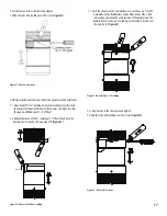
Flange to flange length adjustment can range from 7”x 281/2” 

NOTE:

 If the flue is too long to fit into the adjacent section of duct without

interfering with the flow path, it should be trimmed to desired 

flange to flange length plus an overlap of 4” with the inner wall of

the inlet end duct section. The minimum overlap for the outer casing 

is 1” with the inlet end section outer wall. 

(See Figure 33 & 35a).

NOTE:

 If an LV joint must be joined to one of these fittings, the unflanged 

end of the tube should always point downward or towards 

downward slope. 

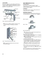
Figure 33 - Overlap Details for Variable Length

INSTALLATION STEPS FOR THE VARIABLE LENGTH (LV)  

(DSLS-DSLD)

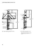
Step 1

- Measure the distance X required for the variable length. See 

Figure 34.

Figure 34-Step 1 for Installation of Variable length

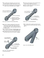
Step 2 

- Cut the inner wall at the dimension X found at the first Step plus 

4”. See 

Figure 35a. 

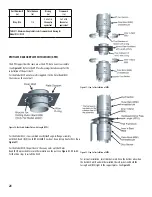
Step 3

 - Cut the split outer casing on the opposite side of the flanged half  

at dimension X plus 1’’. See 

Figure 35b.

Figure 35a -Step 2 -
Cut of the Sliding Inner Wall

Figure 35b - Step 3 -
Cut of the Outer Casing

Cut Split Outer

casing to X + 1”

Cut Sliding Inner

Wall to X + 4”

Distance ”X”

23

Содержание DuraSeal DS

Страница 1: ...g damage prior to installation B Proper joint assembly is essential for a safe installation Follow these instruc tions exactly as written Check severeness of joints upon completion of assembly C This...

Страница 2: ...ory I II III and IV in USA UL 1738 or in Canada asType BH GasVenting as noted in ULC S636 with a maximum operating temperature of 480 F 250 C and a maximum rated positive pressure of 35 water column I...

Страница 3: ...y do not overheat at points of contact Notes 1 Unenclosedrequiresatleasttwosidesopen 2 SingleWall DS DSLS maybeenclosedonlyinnon combustibleenclosure 3 Reducedclearancesmaybeattainedbyusingnon combust...

Страница 4: ...bing or electrical systems Maintain rated clearances to combustibles over the entire length of the vent system DuraSeal shall not be routed into through or within any vent such as an existing masonry...

Страница 5: ...25 70 6 90 90 90 45 90 45 65 7 87 5 87 5 87 5 43 75 87 5 43 75 55 8 85 85 85 42 5 85 42 5 50 9 N A N A N A N A N A N A N A 10 80 80 85 42 5 85 42 5 40 12 75 75 75 37 5 75 37 5 30 14 70 70 70 35 70 35...

Страница 6: ...etween Guides Supports MDE Maximum Distance between Elbows H Maximum Freestanding Height above the Roof S Maximum Suspended Length SUPPORTANDGUIDESPACINGFORMODELDS DSLS Inside diameter MVS MHS MDE H S...

Страница 7: ...ance manufacturer are permitted 4 Thetotalcontinuousdistanceoftheventsystemfromtheapplianceflue collartotheterminationshallnotexceedthatspecifiedintheappliance manufacturer sinstallationinstructions W...

Страница 8: ...himble WTI OPENING DIMENSIONS FORWALL ROOF PENETRATION FOR MODEL DSID Inside Diameter WallThimble WT Wall Thimble Insulated WTI Roof Thimble RT Roof Thimble Insulated RTI 3 10x10 11x11 7x7 11x11 4 13...

Страница 9: ...appliance 1 ADrainlength DL oraTeewithadrainteecap DTC isstronglyrecom mended Installthisdrainascloseaspossibletotheappliancefluecollar 2 A condensate drain is required for every 30 feet of horizontal...

Страница 10: ...t SeeTable 7 8 MHS 30 Termination STA Opening dimension SeeTable 9 10 11 WallThimble WT WTI Roof Support RS Suspension Band SB Anchor Plate HD APHD Appliance Maximum distance suspended SeeTable7 8 S F...

Страница 11: ...TI Maximum distance between guides SeeTable 7 8 MVS Opening dimension SeeTable 9 10 11 Minimum Clearance SeeTable 1 Maximum distance between supports SeeTable 3 4 5 6 Maximum distance between elbows w...

Страница 12: ...oz 3 0 1 4 0 1 5 0 1 6 0 1 7 0 1 8 0 2 9 0 2 10 0 2 12 0 3 14 0 3 16 0 3 18 0 4 20 0 4 22 0 5 24 0 5 Table 12 Figure 9 Position of Support Important Notes DS DSD DSID ONLY 1 For Anchor Plate AP Anchor...

Страница 13: ...should be used NOTE The adjustable length is a non load bearing part A support must be used after it to take the load of the sections above NOTE The inner conduit may be cut to desired length to limi...

Страница 14: ...o the same chimney or vent Elbow or tee Guy support GS Centering band CB Stainless steel wire rope by other Combustible wall Masonry chimney 1 Minimum Exit cone EC Maximum distance between guides See...

Страница 15: ...he Flex Flex adapter with the flexible liner 1 Before official installation 1 1 If cutting the liner on the field is required make sure the cut is square Make a marker line on both ends of the liner a...

Страница 16: ...FlexVi ton caulking 2 2 Push the adapter on the liner all the way in until you can t seethe mark made on the flexible liner earlier Figure 19 Make sure that theViton caulking is sealed well at the joi...

Страница 17: ...ofViton caulking at 1 2 from the edge of the flexible liner all around the inner side of it Figure 22 Figure 22 DuraSeal FlexViton caulking 3 3 Push the adapter on the liner all the way in until you...

Страница 18: ...ed 2 Make sure the DuraSeal Flex is supported at the bottom of the chimney Refer to Figure 12 forguiding and support installation in the masonry chimney 3 The DuraSeal Flex liner must be installed fro...

Страница 19: ...19 SECTION C SPECIFIC INFORMATION MODELS DSLS DSLD 26 TO 36 TYPICAL INSTALLATION FOR DSLS DSLD Figure 26 Typical installation for DSLD...

Страница 20: ...the value In theTable 7 8 use bracing or cable guying to staballze chimney section above the roof See Figure 27 Figure 27 Height with rigid bracing or guying option for DSLS DSLD Figure 28 Maximum fre...

Страница 21: ...lation add a bead of blackViton caulking over the Viton O ring NOTE Sealant Caulking is supplied by DuraVent and Individual tubes are marked Fluorodyn Caulk VITON code VITON S 2 5 oZ VITON L 11 oZ It...

Страница 22: ...to the inside of the inner flue adjacent to the nipple to channel the effluent to the drain 3 The duct drain is intended for use at the end of a horizontal run where access and drainage is needed see...

Страница 23: ...ged end of the tube should always point downward or towards downward slope Figure 33 Overlap Details forVariable Length INSTALLATION STEPS FORTHEVARIABLE LENGTH LV DSLS DSLD Step 1 Measure the distanc...

Страница 24: ...regular length installation See JOINT ASSEMBLY section Step 8 Apply thin layer of sealant inside the retaining collar and also a continuous bead of sealant at the collar overlap seam See Figure 37 Fig...

Страница 25: ...lations and must be connected to a suitable disposable point It can also be used as an access for clean outs or access purposes See Figure 41 Same installation as aTee Cap TC ELBOWS DSLS DSLD ELBOWS E...

Страница 26: ...by threaded rods or from small size angles or straps are usually not satisfactory to resist bending moments due to offsets Figure 44 Maximum Spacing between supports for Offset ADAPTERS DSLS DSLD TAPE...

Страница 27: ...members are supplied by the installer See Figure 48a and 48b Figure 48a Ventilated Anchor Plate on a Framework Figure 48b Detail of theVentilated Anchor Plate on a Framework Supported duct sections in...

Страница 28: ...the part doesn t have any outer wall but Outer Band BSE is provided to secure the insulation on the part See Figure 51 52 53 for the three steps to install the DSLD Figure 50 Ventilated Anchor Plate...

Страница 29: ...of the flange band The Heavy DutyWall Support Assembly is bolted together with provided hardware It is made with adjustable struts which allows a variable clearance from the non combustible wall to t...

Страница 30: ...hardware provided to form a rigid assembly NOTE Seal joint with S 375 sealant above and below support if exposed to weather FULL ANGLE RING FAR A Full Angle Ring is used as a guide to prevent the duc...

Страница 31: ...n the vertical position The inlet and outlet ends must each be supported TEE SUPPORT TheTees must be supported properly to protect them from bending It can be done by means of Anchor Plate AP Anchor P...

Страница 32: ...pitch 5 to 30 See Figure 64 Figure 62 Storm Collar Figure 63 Flashing Figure 64 Adjustable Flashing NOTE The flashings are non ventilated and does not provide for any reduced clearance to combustible...

Страница 33: ...tem incorporates a drain hose from either a Drain length or a Drain tee cap the hose must be inspected periodically to ensure that water is in the trap loop If a proper trap loop is not maintained exh...

Страница 34: ...07 14 17 DuraVent Limited reserves the right to make changes at any time without notice in design materials specifications prices Consult your local distributor for chimney system code information 10...

Отзывы: