16
EXTERIOR INSTALLATION (CONT’D)
Step 2. Place the exterior half of the Wall Thimble
(WTI) in the opening from the outside. Fasten
in place using (4) 2” nails or 1” screws. This
Wall Thimble is adjustable from 7” to 12”. Cut
the insulation pad (included) to match the wall
thickness.
Step 3. Slide the interior half of the wall thimble inside
the exterior half of the wall thimble.
Step 4. Use a level to ensure the wall thimble assem-
bly is level, then fix the thimble in place using
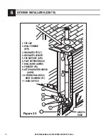
the screws provided (see Figure 19). For a wall
requiring more then 12”, a shield extension
can be field fabricated using galvanized sheet
metal 26 gauge minimum to cover the gap.
6
NOTE: DIAGRAMS & ILLUSTRATIONS ARE NOT TO SCALE.
FRAME OPENING
CHIMNEY SIZE
COMBUSTIBLE
CONCRETE
6"
14’’ x 14’’
10-1/4’’
7"
15’’ x 15’’
11-1/4’’
8"
16’’ x 16’’
12-1/4’’
INSTALLATION INSTRUCTIONS
Step 1. Determine where the chimney will pass
through the wall.
• For concrete walls cut a hole slightly larger than
the chimney.
NOTE:
Wall thimble not required with concrete.
• For combustible walls cut and frame a hole 4”
larger than the chimney, midway between the wall
studs (see Table 8 below for sizing).
See Figure 18
Wall studs are typically placed at 16” centers. If the
opening is perfectly centered, the studs on either
side can be used to hang the tee support. This will
ensure a strong attachment to the exterior wall.
Table 8
NOTE:
The cavity surrounding the outer radiation
shield and the wood frame must be filled with
insulation (see Figure 19).
Step 5. Attach the clean out cap to the support or
directly to tee bottom depending on configu-
ration. (see Figures 16) The cap is in the box
with the insulated tee.
Step 6. The minimum length of insulated chimney
required to pass through the wall will be its total
thickness plus 7". The insulated chimney must
project at least 5” into the room beyond the
finished wall. Attach horizontal chimney length
to the tee’s branch. Turn it clockwise to lock
it in place. Seal the joint between the tee and
horizontal length using the supplied length of
foil-faced tape. Place the insulated tee on the
support with horizontal chimney length posi-
tioned through the wall.
NOTE
: The supports (ATSC) or (URES) can be installed
above the tee. See Figure 17.
Step 7. This step will require 2 people: (See Figure 16).
Insert the chimney length of this tee-support
assembly into the frame opening in the wall.
Using a level, ensure the tee is vertical, then
attach the support to the wall using (8) Nº. 10
x 1 - 1/4" wood screws or 4" spiral nails.
NOTE:
To provide sufficient strength, the nails
must be driven into the wall studs. For concrete
walls, the support should be attached using
(8) 1/4" x 2" lag bolts.
Step 8. From inside, attach the flue extension
(CA) to the horizontal chimney length (see
Figure 16).


