5
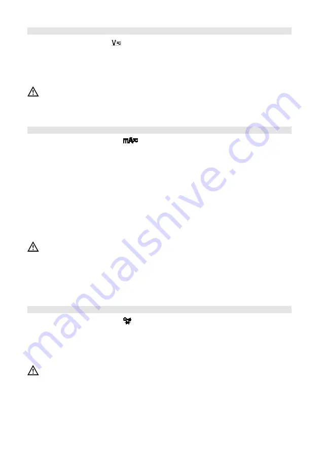
AC & DC VOLTAGE MEASUREMENT
•
Move the rotary dial to
, press the “FUNC.” button and select DC or AC voltage
measurement.
•
Connect the probe to be measured to the circuit or power supply in parallel and
measure the voltage.
•
Read the measurement on the screen. When measuring DC voltage, the display
also shows the voltage polarity of the red probe test point.
Warning
•
Do not input voltage above 600V as there is a risk of damaging the instrument.
•
After completing all measurements, always disconnect the probe and the
measured circuit.
AC & DC CURRENT MEASUREMENT
•
Move the rotary dial to the
position, press the “FUNC.” button and select DC
or AC current measurement.
•
Cut off the power supply to the measured circuit and discharge all of the high
voltage capacitors on the measured circuit.
•
Disconnect the circuit to be tested and connect the instrument to the circuit to be
measured in series.
•
Connect to the power supply of the circuit and then read the measurement on the
screen. When measuring DC current, the display also shows the voltage polarity of
the red probe test point.
Note: If “OL” is displayed it means that the instrument exceeds the measurement range
of the instrument.
•
Disconnect the circuit to be tested, remove the probe of the instrument and restore
the circuit.
Warning
•
Do not input current above 200mA, otherwise the fuse in the instrument may be
burned.
•
Disconnect the power supply of the measured circuit firstly and fully discharge all
high voltage capacitors, then connect the instrument to the circuit in series.
•
After completing all measurements, always disconnect the probe and the
measured circuit.
RESISTANCE MEASUREMENT
•
Move the rotary dial to the position. Note: If it’s not in the resistance
measurement function, press “FUNC.” to switch to resistance measurement
function.
•
Connect the probe to the circuit to be measured in parallel and measure the
resistance.
•
Read the measurement result of the screen.
Warning
•
Firstly, disconnect the power supply of the circuit to be measured and fully
discharge all high voltage capacitors.
•
After completing all measurements, always disconnect the probe and the
measured circuit.
Содержание D03127
Страница 1: ...1 MODEL D03127 Digital Multimeter Pen Type...


