


www.duralloy.net.au
|
1300 369 456
11
171
& 191
MULTIMIG
OWNER’S MANUAL
2. Wire Feed Speed
. Increase in wire feed speed increases
weld current, Decrease in wire feed speed decreases weld
current
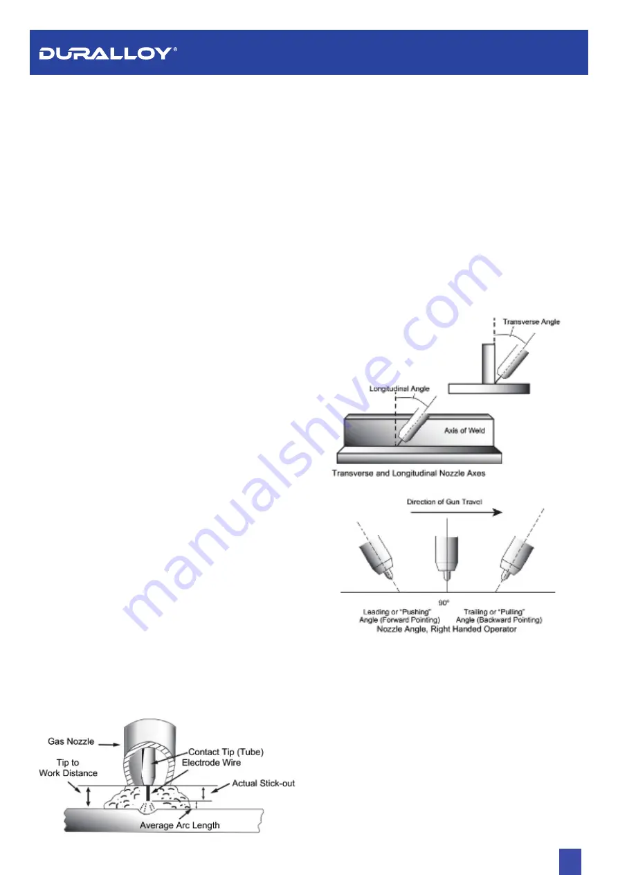
3. Nozzle Angle
. This refers to the position of the welding gun
in relation to the joint. The transverse angle is usually one
half the included angle between plates forming the joint. The
longitudinal angle is the angle between the Centre line of the
welding gun and a line perpendicular to the axis of the weld.
The longitudinal angle is generally called the Nozzle
Angle and can be either trailing (pulling) or leading
(Pushing). Whether the operator is left handed or right
handed has to be considered to realize the effects of each
angle in relation to the direction of travel.
The electrode wire stick out from the MIG Torch nozzle should be
between 10mm to 20.0mm. This distance may vary depending on
the type of joint that is being welded
Travel Speed
•
The speed at which the molten pool travels influences the
width of the weld and penetration of the welding run
MIG Welding (GMAW) Variables
•
Most of the welding done by all processes is on
carbon steel. The items below describe the welding.
•
Variables in short-arc welding of 24gauge (0.024”, 0.6mm) to
¼” (6.4mm) mild sheet or plate. The applied techniques and
end results in the GMAW process are controlled by these
variables.
Preselected Variables
•
Preselected variables depend upon the type of material
being welded, the thickness of the material, the welding
position, the deposition rate and the mechanical properties.
These variables are:
•
Type of electrode wire
•
Size of electrode wire
•
Type of gas (not applicable to self-shielding wires FCAW)
•
Gas flow rate (not applicable to self-shielding wires FCAW)
Primary Adjustable Variables
•
These control the process after preselected variables have
been found. They control the penetration, bead width, bead
height, arc stability, deposition rate and weld soundness.
They are:
•
Arc Voltage
•
Welding current (wire feed speed)
•
Travel speed
Secondary Adjustable Variables
These variables cause changes in primary adjustable variables
which in turn cause the desired change in the bead formation.
They are:
1.
Stick-out
(distance between the end of the contact tube (tip)
and the end of the electrode wire). Maintain at about 10mm
stick-out
DISTANCE FROM THE MIG TORCH NOZZLE TO THE WORK PIECE
ESTABLISHING THE ARC AND MAKING WELD BEADS
Before attempting to weld on a finished piece of work, it is
recommended that practice welds be made on a sample metal of
the same material as that of the finished piece
The easiest welding procedure for the beginner to experiment
with MIG welding is the flat position. The equipment is capable of
flat, vertical and overhead positions.
For practicing MIG welding, secure some pieces of 16 or 18
gauge (0.06” 1.5mm or 0.08” 2.0mm) mild steel plate 6” x 6” (150
x 150mm). Use 0.030” (0.8mm) flux cored gasless wire or a solid
wire with shielding gas
Содержание 171 MULTIMIG
Страница 1: ...171 191 MULTIMIG OWNER S MANUAL www duralloy net au 1300 369 456...
Страница 18: ...www duralloy net au 1300 369 456 18 171 191 MULTIMIG OWNER S MANUAL 11 3 Wire feeder 11 4 Cables...
Страница 19: ...www duralloy net au 1300 369 456 19 171 191 MULTIMIG OWNER S MANUAL CONNECTION DIAGRAM OF THE MACHINE...
Страница 20: ...www duralloy net au 1300 369 456 20 171 191 MULTIMIG OWNER S MANUAL EXPLODED DRAWING...
Страница 22: ...www duralloy net au 1300 369 456...