5.0 MAINTENANCE
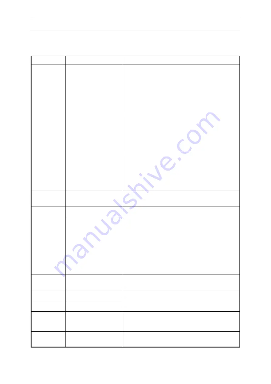
5.9 TROUBLESHOOTING
SYMPTOM
POSSIBLE CAUSE
REMEDY
1. Unit will not
start.
a.) Power off.
b.) No control power.
c.) Compressor circuit
breakers open.
d.) Undervoltage relay open.
e.) Flow Switch open.
f.) Compressor switch open.
g.) Microcomputer shutdown
not reset.
a.) Check main disconnect switch and main line fuses.
b.) Check control transformer fusing.
c.) Close circuit breakers. If trip, check compressor.
d.) Check for power supply problems (low voltage, phase
imbalance). When corrected, press reset button.
e.) Start pumps, check flow switch.
f.) Turn switch on. Check alarm status. Correct problem.
g.) Press reset button.
2. Compressor
hums but
does not
start.
a.) Low voltage.
b.) No power on one phase
of 3 phase unit.
c.) Faulty starter or
contactor.
a.) Check at main entrance and at unit. Consult power
company if voltage is low and increase wire size to the
unit if voltage is normal at main and low at unit. Voltage
must be within 10% of motor nameplate rating.
b.) Check fuses and wiring.
c.) Check the contacts and time delay on part wind start.
3. Compressor
will not start
when reset
button is
pushed.
Check light:
None
a.) Cooling not required.
b.) Computer's time delay
active.
c.) Undervoltage relay open.
d.) Flow switch open.
e.) Compressor switch open.
f.) Burned out signal light.
i.) Wiring problem
a.) Apply load.
b.) Wait 15 minutes max.
c.) See 1.( d.) above.
d.) See 1.( e.) above.
e.) See 1.( f.) above.
f.) Check signal light bulbs.
i.) Check wiring against drawing.
4. Compressor
overload.
a.) Compressor drawing high
amps.
a.) Check motor megohms. Reset overloads , run com-
presssor an check amps. Do not exceed RL x 1.25. Call
D/B serviceman.
5. High motor
temperature
a.) Motor windings failing.
a.) Check megohms. Reset by turning compressor switch off
and then on.
6. Low suction
a.) Inadequate feed to
Evaporator.
b.) Inadequate refrigerant
charge.
c.) Fouling of water side of
Evaporator.
d.) Inadequate chilled water
flow.
e.) Too much oil in system.
a.) Check to see that main expansion valve superheat.
b.) See information on charging in Section 5.7
c.) At high load, check Evaporator approach (See Section
5.4). If approach is more than 2°F above clean valve,
fouling is probably the trouble. Clean tube.
d.) Measure pressure drop across vessel and determine gpm
from Figure 3.3. If gpm is low, check chilled water pump,
valves and strainers.
e.) If all oil level sight glasses are full at all times, remove oil
until oil level shows at top of glass on a compressor.
7. High
discharge
pressure.
a.) Inadequate air flow
across condenser
a.) Check condenser fan operation and condenser coil for
clogging.
8. Oil low in
sump.
a.) Low oil level in
compressor.
a.) Low oil level in compressor sight glass is acceptable.
9. Low oil
shutdown.
a.) Low oil in compressor.
a.) See Section 5.7.2.
10.Freeze
warning.
a.) Operating setpoint too
low.
b.) Load changing too
rapidly.
a.) Check leaving water setpoint on microcomputer.
b.) Load on package must drop at reasonable rate for
automatic control to work properly.
11.Improper
capacity
control.
a.) Ramp rate incorrect.
a.) See Section 4.5.5.
- 42 -
Содержание ACXi 165-5SP-LN
Страница 6: ...2 0 INSTALLATION FIGURE 2 3 2 ACXi 165 5SP LN TYPICAL RIGGING 6...
Страница 9: ...2 0 INSTALLATION FIGURE 2 4 2 ACXi 165 5SP LN DIMENSIONAL DATA NOTE ALL DIMENSIONS ARE IN INCHES MM 9...
Страница 14: ...3 0 OPERATION FIGURE 3 2 ACXi 165 5SP LN TYPICAL SCHEMATIC PIPING 14...
Страница 20: ...CHECKED REV NO DATE APPROV 4 0 ELECTRICAL FIGURE 4 2 ACXi 165 5SP LN WIRING SCHEMATIC 20...
Страница 21: ...4 0 ELECTRICAL 21...
Страница 22: ...4 0 ELECTRICAL 22...
Страница 23: ...4 0 ELECTRICAL 23...
Страница 24: ...4 0 ELECTRICAL 24...
Страница 25: ...4 0 ELECTRICAL 25...
Страница 26: ...4 0 ELECTRICAL 26...
Страница 27: ...4 0 ELECTRICAL 27...
Страница 28: ...4 0 ELECTRICAL 28...
Страница 29: ...4 0 ELECTRICAL 29...
Страница 30: ...4 0 ELECTRICAL 30...
Страница 31: ...4 0 ELECTRICAL 31...


