background image

10

and one pin drops into hole. (Note: spacer nut should 
not be rotated more than 221/2 before pin drops into 
hole in gear.) It is preferable to tighten spacer nut 
down instead of loosening.

25.  Remove pin from aligned hole. Install half dog set 

screw (68) and tighten half dog point into hole in 
output gear (39). Remove remaining pin and proceed 
with assembly. Note: One hole must be in alignment 
to have proper assembly.

26.  Lightly grease O.D. of translating tube (66) with 

Duboise M.P.G. grease (no substitutes) and assemble 
outer tube (55) assembly over translating tube (66) 
and thread into housing (42) (a sealing compound 
such as Non-Hardening Permatex 2 should be used 
on threads).

27. Insert intermediate pinion shaft (32) in housing (42)    

and place thrust washer (31) over shaft (32).  


Assemble intermediate cluster gear (33) on shaft  
and place thrust washer (31) on top.

28.  Assemble bearing (28) on input pinion (29) (press on 

inner bearing ring to prevent damage to bearing).

29.  Pack housing (42) gear box cavity with Aeroshell #6 

grease (no substitutes).

30.  Assembly of Motor (53) to Housing (42)


a.  Note location of flat on input pinion by marking 

spot on the housing. See Figure 6-1B.


b.  Insert grommet (50) on input pinion (29) between 

coupling (47) posts and install “O”-Ring (52) in 
cavity of insert (51).


c.   Pack cavity with Aeroshell #6 grease.


d.   If hole plug (54) is in rear end of motor, remove.


e.   Feed motor (53) lead wires through hole in 

housing (42) lining up couplings (47) on input 
pinion (29) and motor (53) shaft. (Alignment is 
critical at this point. See Figure 6-1B.)

NOTE

Input pinion (29) and motor (53) shaft flats are 

opposite each other.


f.  Assemble motor (53) into housing (42) . Before 

assembling lock washers (46) and socket head 

screws (45), hold motor firmly in place and, 

with a screwdriver, turn motor shaft by using 
screwdriver slot in end of motor shaft.

NOTE

Before turning motor shaft, make sure pinion shaft 
has not been pushed out. It may be necessary to 
hold pinion shaft down while turning motor shaft. If 
couplings are properly installed, the motor can be 
turned freely in both directions. If motor shaft will not 
turn, this is an indication that couplings are not properly 
aligned and assembly should be corrected.


g.  Install lock washers (46) & socket head screws (45).

31.  Insert dowel pins (27) in housing (42) and place 

gasket (41) in place over dowel pins (27).

32.  Install air vent (58) in outer tube (55) ( it may be 

necessary to back outer tube out in order to install air 
vent or to have vent in a more desireable position).  
Spot drill tube and install set screw (33) to hold tube 
in place.

33. Install spring (61) into end of screw (62).

NOTE

If unit has potentiometer assembly (26) and gear 
(26b) does not have to be replaced or if unit has no 
potentiometer feature, proceed to Step 35.

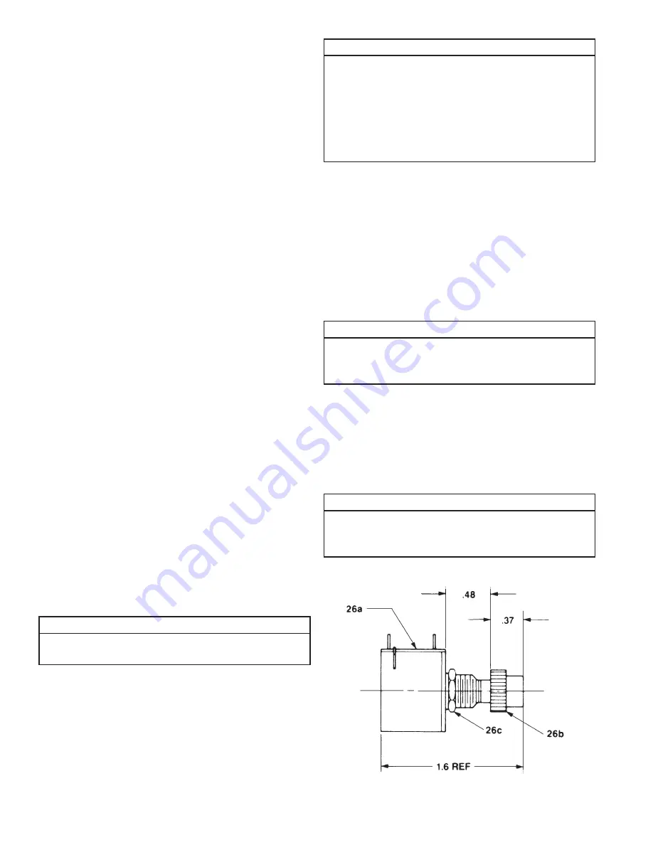
34.  Potentiometer Assembly (26)
 

a.  If nut and washer were removed from 

potentiometer, assemble washer (26d) and nut 
(26c) on potentiometer (26a). Nut (26c) should 
not be tightened on potentiometer (26a) face.


b.  Assemble gear (26b) on potentiometer (26a) shaft.

NOTE

Gear should be assembled with a very light press. 
See sketch for required dimension of gear on 
potentiometer. Take care not to damage potentiometer.

35. 

Assembly of Cover (9)

Figure 4-1.  Potentiometer Nut & Washer 

 Assembly

Содержание 6415 Series

Страница 1: ...bed herein All persons involved in such installation operation and maintenance should be thoroughly familiar with the contents To safeguard against the possibility of personal injury or property damag...

Страница 2: ...tentiometer Installation 5 2 5 Digital Position Indicator 6 Section III Operation 3 1 Operational Procedures 6 Section IV Maintenance 4 1 Lubrication 7 4 2 Required Tools 7 4 3 General Procedures 7 4...

Страница 3: ...or abrasive action excessive heat or other abuse Equipment and accessories not of Duff Norton s manufacture are warranted only to the extent that they are warranted by their manufacturer and only if t...

Страница 4: ...ion type Load no0load speeds are approximately Figure 1 1 SPA 6415 and SPA 7415 Technical Illustration Figure 1 2 Limit Switch Wire Color Diagram equal Equipped with thermal overload which opens and r...

Страница 5: ...toward the extended position until the distance between the housing clevis hole centerline and the translating tube clevis hole centerline equals the desired extended height This centerline to center...

Страница 6: ...alculations See detailed instructions with the SK6300 4K indicator for installation and programming instructions Potentiometer terminal CCW should be connected to indicator Common CW to Excitation Vol...

Страница 7: ...ON Take care not to damage potentiometer when removing gear 4 Remove screws 1 from capacitor box cover 2 and remove cover 2 and gasket 3 Remove insulation 4 from capacitor box 5 Discharge capacitor 5...

Страница 8: ...translating tube wall then remove the translating tube from the nut 31 Remove the lifting screw 62 from the lifting nut 64 32 Remove the four pins 65 by pressing each one the rest of the way through t...

Страница 9: ...be loose in cover 12 Attach red terminal wire 17 to common terminal of left side switch 16 Attach blue terminal wire 18 to common terminal of right side switch 16 Feed ends of terminal wires 17 and 18...

Страница 10: ...this point See Figure 6 1B NOTE Input pinion 29 and motor 53 shaft flats are opposite each other f Assemble motor 53 into housing 42 Before assembling lock washers 46 and socket head screws 45 hold m...

Страница 11: ...of switch Wires going to switches should be same color It may be necessary to install terminals on switch terminals tabs with needle nose pliers and care should be taken not to damage terminal tab or...

Страница 12: ...ft IntermediateClusterGear Bushing Thrust Washer Thrust Bearing 2 1 1 2 4 2 255K14 SK 6415 9 SK 6415 4 SK 6415 11 255K10 511K11 Index No Part Name Qty Req Part Number 37 38 39 40 41 Spacer Nut Set Scr...

Страница 13: ...ed Parts Illustration 6415 7415 Series AC Actuator WARNING Use only replacement parts supplied by or approved by Duff Norton Non authorized parts may be inadequate resulting in serious injury or death...

Страница 14: ...ure 6 1A Brake Spring Motor and Pinion Coupling Alignment Figure 6 2 Limit Switch Wiring Diagram 6415 7415 Series AC Actuator Figure 6 3 Limit Switch Assembly 6415 7415 Series AC Actuator Figure 6 1B...

Страница 15: ...15 Notes...

Страница 16: ...tures Mechanical Actuators Rotary Unions Mechanical Jacks Electromagnetic Actuators 2020 Duff Norton A Columbus McKinnon Company All rights reserved 9415 Pioneer Avenue Suite 100 Charlotte NC 28273 80...

Отзывы: