background image

Contatto

ModDALI

Point

Description

1

Current brightness

2
3
4
5
6
7
8
9

-

10

-

11

Polling disabled

12

Power supply loss on DALI side

13

Test button pressed

14

Lamp failure

15

DALI line broken

16

DALI line short circuit

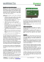
The first available information (the 8 lower bits of the chan-
nel) is the brightness level of the ballast having address 1
on each DALI line (assumed as reference for all the other
ballasts). Thus, to use this function, the ballasts have to be
addressed starting from address 1. The value of the current
brightness level is in the range 0 to 100; if no ballast has
been addressed as 1, then the reported value will be 255.
A lamp failure condition will be instead reported by the val-
ue 128; if the answer from the ballast will not be under-
stood the value 129 will be reported.

If the brightness level of each ballast on each DALI line is
required by the application, a script for MCP is available for
this purpose; contact 

DUEMMEGI

 for more information.

Output section

4 channels 16 bit are available on the output address for
the execution of commands to the ballasts, as described in
the following table:

Point

Description

1

Function

2
3
4
5
6
7
8
9

Destination

10
11
12
13
14
15
16

DUEMMEGI

 s.r.l. - Via Longhena, 4 - 20139 MILANO

Tel. 02/57300377 - Fax 02/55213686 – 

www.duemmegi.it

Rel.: 2.4 October 2017

Page 3 of 9

Figure 2: Wiring connections for special version (2-line / 64-ballast)

Power supply      24V=  

25% / 45mA

+2

4V

0V

L1

L2

P

1

14

16 17

15

Contatto

DUEMMEGI

MILANO-ITALY

2

3

4

5

6

7

8

13

19 20

ON

D

A

+

D

A

-

D

A

+

D

A

-

D

A

+

D

A

-

D

A

+

D

A

-

ADDRESS

MODDALI

DALI

SUPPLY

OUT

IN

DALI Gateway 

+24V

BUS

0V

L1

L2

AUX

SUPPLY

12V~ 

15÷24V=


DALI

1

DALI

64

DALI

1

DALI

64

9

A

B

C

D

Содержание CONTATTO ModDALI

Страница 1: ...ALI module provides a 5 way terminal blocks for the connection to Contatto bus a 2 way terminal block for the supply voltage of DALI section and a 9 way terminal blocks for the connection to the 4 DAL...

Страница 2: ...llowing table gives some rules for the MINIMUM ca ble section As said above no special cables are required for the 4 DALI lines provided that they have double insula tion In any case the distance betw...

Страница 3: ...ballast will not be under stood the value 129 will be reported If the brightness level of each ballast on each DALI line is required by the application a script for MCP is available for this purpose c...

Страница 4: ...t level The code 113 enable again the polling the current status of the polling is re ported bu the point 11 of the input channel if enabled At the module power up or after a reset the polling is alwa...

Страница 5: ...ting parameters of each DALI channel and to perform some diagnostic functions The setting up is performed via the Contatto bus and MCP through a specific configuration panel which can be opened select...

Страница 6: ...tion of the mapping procedure pressing the but ton Start will take place only for the ballasts selected by the related checkbox A timer icon will inform that the oper ation is running At the end of th...

Страница 7: ...ake in account that it is not pos sible to read from ModDALI module the current settings of the groups therefore it is strongly recommended to save them into a file for future modifications Global Set...

Страница 8: ...ry each scenery will be a file Commands This tab provides a several commands belonging to DALI protocol this section is addressed to highly qualified staff so it is recommended not to use it if you ar...

Страница 9: ...d the wiring of the Contatto bus line and the re lated devices must be performed according to the recommenda tions of the manufacturers reported on the specific data sheet of the product and according...

Отзывы: