Flash and DMI Utility
27
Use the
←→
(left-right) cursors to move the top menu items and the
↑↓
(up-down) cursor to
move between the left hand menu items. The bottom of the screen will show the available
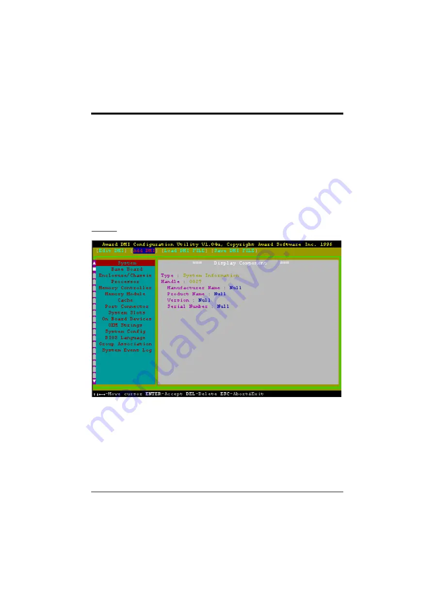
keys for each screen. Press enter at the menu item to enter the right hand screen for editing.
“Edit component” appears on top. The reversed color field is the current cursor position and
the blue text are available for editing. The orange text shows auto-detected information and
are not available for editing. The blue text “Press [ENTER] for detail” contains a second
pop-up menu is available, use the + - (plus-minus) keys to change the settings. Enter to exit
and save, ESC to exit and not save.
If the user has made changes, ESC will prompt you to answer Y or N. Enter Y to go back to
the left-hand screen and save, enter N to go back to left-hand screen and not save. If editing
has not been made, ESC will send you back to the left hand menu without any messages.
Add DMI
This DMI Configuration Utility also allows the system integrator or end user to add
additional information into the DMI database such as serial numbers, housing configurations,
and vendor information. Those information not detected by the motherboard BIOS and has to
be manually entered through the DMI Configuration Utility and updated into the DMI
database.
Содержание PRM-68I
Страница 2: ......
Страница 4: ...II change without notice ...
Страница 9: ...Introduction 3 Fig 1 Key Components of the Mainboard ...
Страница 10: ...Chapter 1 4 ...
Страница 12: ...Chapter 2 6 2 2 GRAPHICAL DESCRIPTION OF JUMPER SETTINGS Fig 2 Jumper Location of the mainboard ...
Страница 16: ...Chapter 2 10 ...
Страница 18: ...Chapter 2 12 ...
Страница 19: ...Connector Configuration 13 Fig 4a Optional GOI 660 Extension Card Fig 4b Optional GOI 611 Extension Card ...
Страница 27: ...21 ...
Страница 38: ...Appendix A 32 APPENDIX B PIN ASSIGNMENTS OF EISA SLOT ...


