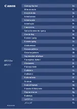
Find
a
pattern
with
a
square
in
the
lightest
color
and
horizontal
lines
on
both
sides
aligned.
A
value
on
the
upper
of
the
pattern
indicates
an
appropriate
adjustment
value.
An
appropriate
adjustment
value
is
“+6”.
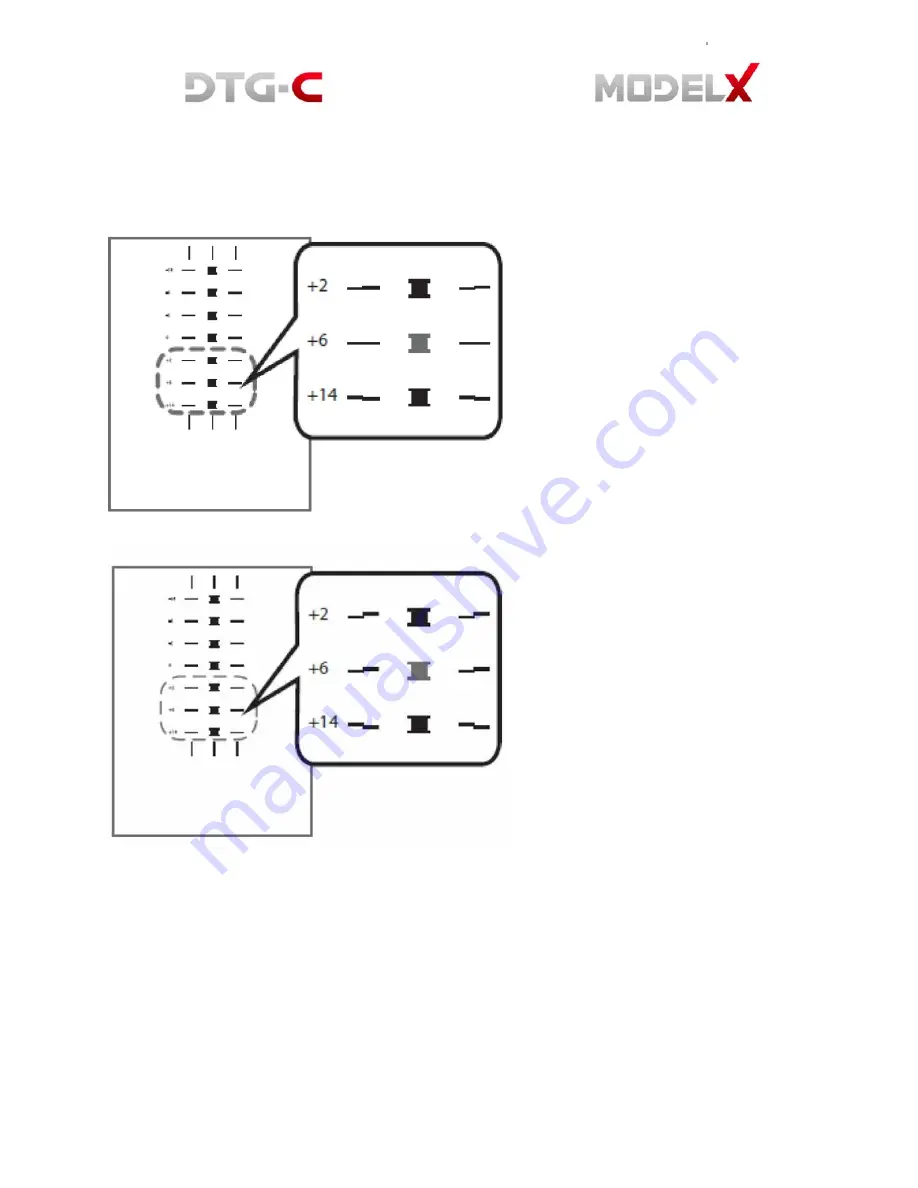
In
some
cases,
an
adjustment
value
is
an
in
‐
between
value
of
patterns
When
a
square
is
in
the
lightest
colour
but
horizontal
lines
on
both
sides
are
misaligned.
In
the
this
illustration
a
square
in
the
lightest
colour
is
“+6”,
but
horizontal
lines
on
both
sides
are
misaligned.
In
this
case
check
horizontal
lines
for
one
pattern
above
and
one
pattern
below
of
the
square.
The
horizontal
lines
for
“+2”
and
“+6”
are
misaligned
in
the
same
direction,
but
the
horizontal
lines
for
“+14”
are
misaligned
in
the
opposite
direction.
In
this
case,
a
value
that
horizontal
lines
align
exists
somewhere
in
between
“+6”
and
“+14”.
After
passing
the
value,
the
horizontal
lines
begin
to
be
misaligned
in
the
opposite
direction
as
getting
closer
to
“+14”
By
referring
to
the
alignment
of
the
lines,
decide
a
value
between
“+6”
and
“+14”
as
an
appropriate
adjustment
value.
Содержание Model X
Страница 1: ......
Страница 18: ...White ink bay Cyan and Black ink bay Magenta and Yellow ink bay Return to home screen...
Страница 26: ...3 USER INTERFACE 3 1 Home Screen 3 1 1 Setting Platen Please refer 2 2 3 Setting Platen...
Страница 39: ......
Страница 50: ...10 Assemble the new ink tube to the ink supply unit 11 Turn on the printer power...
Страница 63: ...the ink pump button on the Replace tab...
Страница 76: ...6 3 Android System Menu 6 4 Printer System Menu 6 4 1 Ink Path Management DBG...
Страница 95: ...84 8 HARDWARE INFORMATION 8 1 Harness Schematics with PCBs...
Страница 103: ...92 9 REPLACEMENT AND ADJUSTMENT FOR SERVICE PART 9 1 Adjustment of X Y Orthogonality...
Страница 104: ...93 0 Lock the 4 Clam ps to Fix the Main Shaft and Sub Sha ft of Bridge 8 Tighten the 6 Rounded Screws on Each Side...
Страница 105: ...94 9 2 Check Head GAP...
Страница 111: ...100 PCB SENC TOS PIE 9 10 Replacing PCB SENC TOS PIE...