PG9994/PG8994/PG4994
PowerG, Wireless, High-security PIR Motion
Outdoor Mirror Detector Installation
Instructions
Overview
The PGx994 is a PowerG wireless, outdoor, digital mirror PIR
detector which uses eight PIR sensors, each acting as a Quad
detector to accurately and reliably determine whether an alarm
is justified. Features & benefits include:
• Optimum performance even in poor weather conditions
such as snow, rain, dust, wind and direct sunlight.
• Tamper protection prevents opening and removal from wall
• Built-in link quality indicators reduce installation time by
eliminating the need for the installer to physically approach
the control panel.
• Microprocessor-controlled compensation.
• Immunity to pets weighing up to 18 Kg (40lb).
Note:
Pet immunity feature has not been evaluated to UL 639
or ULC-S306-03 due to the feature not being addressed in
either standard.
Device Setup
WARNING!
To comply with FCC
and IC RF exposure compliance
requirements, the PIR detector should
be located at a distance of at least 20
cm from all persons during normal
operation. The antennas used for this
product must not be co-located or
operated in conjunction with any
other antenna or transmitter.
Note:
The PG Series wireless PIR
Motion detectors shall be installed
and used within an environment that
provides the pollution degree max 2 and overvoltages category
II in NON HAZARDOUS LOCATIONS. The equipment is
designed to be installed only by qualified service persons.
Note:
To ensure the continued operation of all wireless devices
after performing a system default, a global upload of all wire-
less programming via DLS is recommended before defaulting
the system. After completing the system default, download the
wireless programming.
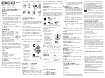
Legend
A. LED
B. Enroll button
C. Tamper switch
D. Bracket release
E. Horizontal view of coverage area
F.
Vertical view of coverage area
G. Vertical angle
H. For wall tamper
Note:
Back tamper switch is required for UL commercial bur-
glary installations.
Install the battery
It is recommended to perform the first batteries insertion on a
flat surface. After battery insertion, the LED will flash for 60
seconds and then the detector will enter a 15 minute local diag-
nostic mode.
Note:
When manually programming wireless devices, if a
device has been powered up for more than 48 hours it cannot be
enrolled into the system until the device has been tampered and
restored. When programming the panel using the Quick Enroll
procedure follow the steps detailed in Enroll the Device into the
System.
Note:
After restoring a low battery trouble the system may take
up to 5 minutes to clear the trouble.
Enroll the Device into the System
To quick enroll:
1.
On a keypad press [*] [8] [Installer Code] [804] [000].
2.
Press and hold the device enroll button until the LED lights
steady and then release the enroll button while the LED is
still lit. A confirmation message then appears on the
keypad.
3.
Press [*] key to confirm ID.
4.
Enter [3 digit zone #].
5.
Enter [3 digit zone type].
6.
Enter [1 digit partition #] for all desired partitions and
press [#]. If using an LCD keypad you can scroll to the
desired partitions and press [*] to toggle the partition.
7.
On an LCD keypad enter the label by using word library.
To pre-enroll:
1.
Remotely configure the unique ID number into the system.
For more information see the HSM2HOST manual.
2.
When on-site, press the device enroll button.
Note:
If the wireless device has been powered for more than 48
hours without being enrolled, tamper and restore the device to
enroll it.
Placement and Walk Testing
Before permanently mounting any wireless device, temporarily
mount the device and perform a Placement test. Perform a walk
test of the coverage area at least once a year to ensure that the
detector is working correctly.
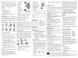
1.
Tamper the device by removing the cover.
2.
Restore the tamper.
The device now
enters Placement
test mode for 15
minutes.
3.
Trip the device and
the red LED blinks
once to identify that
a signal is being sent
to the receiver and
then blinks three
times to identify the
signal strength. To
perform a walk test,
walk across the far
end of coverage
pattern in both
directions. The
following table indicates received signal strength
indication.
IMPORTANT!
Only GOOD or STRONG signal strengths are
acceptable. If you receive a POOR signal from the device, re-
locate it and re-test until a GOOD or STRONG signal is
received.
Note:
For UL/ULC installations, only STRONG signal levels
are acceptable. After installation verify the product functional-
ity in conjunction with the compatible receivers HSM2HOST9,
HS2LCDRF(P)9, HS2ICNRF(P)9 and PG9920.
Note:
For detailed Placement instructions refer to the control
panel Reference Guide.
Mounting the Device
Installation Notes:
The top cover should only be accessed by
authorized service personnel or manufacturer. Do not obscure
the detector field of view with large objects. Install in position
such that expected intruder motion is perpendicular to the zones
of detection.
Alarms triggered by conditions such as weather, blowing leaves
and brush, or related environmental conditions, etc., need to be
considered when assessing the installation and application. If
nuisance trips are not tolerable it is recommended that the wire-
less outdoor intrusion detection unit is enrolled in the system to
a zone that is defined as a trouble alarm circuit.
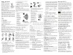
1.
Fix the bracket firmly on a stable wall or pillar. The
orientation of the fixed bracket must be as parallel as
possible to the surveyed ground surface.
2.
Mark drilling point
3.
Drill
4.
Fasten with three long screws
5.
Fasten the detector to the bracket with two short screws.
6.
Adjust the detector's
horizontal and vertical
angles, according to the
surveyed ground surface.
The vertical angle indicator
position for various
installation height and
coverage distance
combinations is detailed in
the following table (the
information refers to a
relatively flat surveyed
area. Verify the vertical
adjustment by walk-test).
LED Operation
Configuration
To enter the wireless configuration section enter [804][Zone
Number].
Device Toggles
Device Options
Specifications
Caution!
Risk of explosion if battery is replaced by an incor-
rect type. Dispose of used batteries according to the manufac-
turer's instructions and according to local rules and regulations.
Batteries are to be replaced by service persons only.
OPTICAL
Black Mirror Max. Coverage:
At least 12 m (40 ft) / 90°
Detector Technology:
8 independent quad PIR detectors oper-
ating in true Quad configuration
Pet Immunity:
Up to 18 Kg (40 lb)
ELECTRICAL
Input Power:
Two 3V CR123A Lithium batteries
Note:
For UL installations use Gold Peak (GP) only.
Battery Life (for typical use):
minimum one year, typical 3
years (not verified by UL/ULC)
Low Battery Threshold:
4.0 V
WIRELESS
Frequency Band (MHz):
CE Listed PG4994: 433MHz; CE/
EN listed PG8994: 868MHz; FCC/IC/UL/ULC listed PG9994:
912-919MHz
Communication Protocol:
PowerG
Tamper Alert Reported when a tamper event occurs and in any
subsequent message, until the tamper switch is restored
MOUNTING
Mounting type:
Wall mounting
Mounting Height:
1.5 – 3.0 m (5 – 10 ft). Must be 8 feet for
UL/ULC listed installations.
Horizontal Adjustment:
-45° to +45°, in 5° steps
Vertical Adjustment:
0° to -10°, in 2.5° steps
ENVIRONMENTAL
Temperature range:
-40ºC to +70ºC (UL/ULC only verified
the range -35ºC to +66ºC)
Relative Humidity:
up to max. 93%RH, non-condensing
White Light Immunity:
Above 25000 lux
PHYSICAL
Size (H x L x W):
157 x 147 x 124 mm (6-3/16 x 5-13/16 x 4-
7/8”)
Weight (with battery):
600 g (21 oz)
Color:
White or gray
COMPATIBLE RECEIVERS
433MHz Band: HSM2HOST4; HS2LCDRF(P)4;HS2IC-
NRF(P)4; PG4920
868MHz Band: HSM2HOST8; HS2LCDRF(P)8; HS2IC-
NRF(P)8;PG8920
912-919MHz Band: HSM2HOST9; HS2LCDRF(P)9; HS2IC-
NRF(P)9; PG9920
Note: Only devices operating in band 912-919MHz are UL/
ULC listed.
UL/ULC Notes
Only models PG9994, PG9994P operating in the frequency
band 912-919MHz are UL/ULC listed. The PG9994, PG9994P
has been listed by UL for commercial and residential burglary
applications and by ULC for residential burglary applications in
accordance with the requirements in the Standards UL 639 and
ULC-S306 for Intrusion Detection Units.
For UL/ULC installations use these device only in conjunction
with compatible DSC wireless receivers: HSM2HOST9,
HS2LCDRF(P)9, HS2ICNRF(P)9 and PG9920. After installa-
tion verify the product functionality in conjunction with the
compatible receiver used.
Europe: The PG4994 and PG8994 are compliant with the RTTE
requirements - Directive 1999/5/EC of the European Parliament and of
the Council of 9 March 1999. The PG8994 is certified by Applica Test
and Certification to the following standards: EN50131-2-2 GRADE 2,
CLASS IV, EN50131-6 Type C. Applica Test andApplica Test and Certification has
certified only the 868 MHz variant of this product. According to EN 50131-1:2006 and
A1:2009, this equipment can be applied in installed systems up to and including
Security Grade 2, Environmental Class II. UK: The PG8994 is suitable for use in
systems installed to conform to PD6662:2010 at Grade 2 and environmental class 2
BS8243. The Power G peripheral devices have two- way communication functionality,
providing additional benefits as described in the technical brochure. This functionality
has not been tested to comply with the respective technical requirements and should
therefore be considered outside the scope of the product’s certification
FCC COMPLIANCE STATEMENT
WARNING! Changes or modifications to this unit not expressly approved by the party
responsible for compliance could void the user’s authority to operate the equipment.
This device has been tested and found to comply with the limits for a Class B digital
device, pursuant to Part 15 of the FCC Rules. These limits are designed to provide
reasonable protection against harmful interference in residential installations. This
equipment generates uses and can radiate radio frequency energy and, if not installed
and used in accordance with the instructions, may cause harmful interference to radio
and television reception.
However, there is no guarantee that interference will not occur in a particular
installation. If this device does cause such interference, which can be verified by
turning the device off and on, the user is encouraged to eliminate the interference by
one or more of the following measures:
– Re-orient or re-locate the receiving antenna.
– Increase the distance between the device and the receiver.
– Connect the device to an outlet on a circuit different from the one that supplies power
to the receiver.
– Consult the dealer or an experienced radio/TV technician.
This equipment complies with FCC and IC RF radiation exposure limits set forth for an
uncontrolled environment.
This device complies with FCC Rules Part 15 and with Industry Canada licence-
exempt RSS standard(s). Operation is subject to the following two conditions: (1) This
device may not cause harmful interference, and (2) this device must accept any
interference that may be received or that may cause undesired operation.
Le present appareil est conforme aux CNR d'Industrie Canada
applicables aux appareils radio exempts de licence. L'exploita-
tion est autorisee aux deux conditions suivantes :(1) l'appareil
ne doit pas produire de brouillage, et (2) l'utilisateur de l'appar-
eil doit accepter tout brouillage radioelectrique subi, meme si le
brouillage est susceptible d'en compromettre le fonctionne-
ment.
PG9994/PG8994/PG4994
Instructions d'installation du détecteur de
mouvements IPR PowerG, à miroir, extérieur,
sans fil, de haute sécurité
Vue d'ensemble
Le PGx994 est un détecteur numérique IPR PowerG à miroir,
extérieur, sans fil qui met en œuvre huit capteurs IPR, chacun
agissant comme un détecteur à quatre cellules pour déterminer
de façon sûre et précise si une alarme est justifiée. Les car-
actéristiques et les avantages incluent :
• Des performances optimales même sous de mauvaises
conditions météorologiques comme de la neige, de la pluie,
du vent, en cas d'exposition à de la poussière ou aux rayons
directs du soleil.
• La protection anti-sabotage empêche le dispositif d'être
ouvert ou retiré du mur.
• Les indicateurs de qualité de liaison intégrés réduisent les
temps d'installation en supprimant la nécessité de
l'installateur d'être physiquement à proximité de la centrale.
• Correction apportée par microprocesseur.
• Insensibilité aux animaux d'un poids jusqu'à 18 kg (40 lb).
Remarque :
La fonction d'insensibilité aux animaux n'a pas été
évaluée pour les normes UL 639 ou ULC-S306-03 parce qu'elle
n'est pas abordée par les deux normes
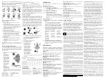
LED response
Signal Strength
Green LED blinks
STRONG
Orange LED blinks
GOOD
Red LED blinks
POOR
No blinks
No communication
C
D
E
F
LED Indications
Event
Red LED blinks
Stabilization (warm-up 60
sec)
Red LED on 0.2 sec.
Tamper open / close
Red LED blinks twice
One quad PIR detection in
diagnostic mode
Red LED on 2 sec.
Intruder alarm
[001][01]
Alarm LED - Default [Y]
Enables the devices LED to activate when an alarm
event occurs.
[001][04]
Supervision - Default [Y]
Enables supervision of the device.
[001][11]
24Hr/ Night - Default [Y]
2
H
3
4
5
G
Mounting
Height
Coverage Distance
2m /
6.7ft
4m /
13ft
6m /
20ft
8m /
26ft
10m/
33 ft
12m/
39 ft
3.0m/10ft
-
1
2
2
3
3
2.5m / 8 ft
1
1
2
3
4
4
2.0m / 7 ft
1
2
3
4
5
5
1.5m / 5 ft
2
3
4
5
-
-
Define whether motion alarms are always enabled
or only enabled at night. For UL/ULC installations
night mode is to only be used to supplement the
protection covering the detection area.
[003]
Hightraffic Shutdown - Default [01]
Activating this feature helps conserve battery power
when the system is disarmed by configuring a reporting
timer. When motion is detected, the device transmits an
alarm to the receiver and will not report any further
events until the timer expires. Any motion detected
during the configured period will be reported once the
timer expires. No Delay causes the device to report an
alarm each time the detector is tripped.
[01] Detector Dis-
abled (while dis-
armed)
[02] No Delay
[03] 5 second
delay
[04] 15 second
delay
[05] 30 second
delay
[06] 1m delay
[07] 5m delay
[08] 10m delay
[09] 20m delay
[10] 60m delay
[007]
Detection Sensitivity - Default [02]
Selects the sensitivity range of PIR devices.
[01] Low Sensi-
tivity
[02] High Sensi-
tivity
[03] UL Standard
D-304675

