background image

1

1 .   I n t r o d u c t i o n

Table of Contents

1.

Introduction  . . . . . . . . . . . . . . . . . . . . . . . . . . . . .1

2.

Specifications  . . . . . . . . . . . . . . . . . . . . . . . . . . . .1
PC4400 connected to a serial printer . . . . . . . . .1
PC4400 connected to a DVAC network  . . . . . .1

3.

Installing the PC4400 . . . . . . . . . . . . . . . . . . . . . .1
3.1

Unpacking . . . . . . . . . . . . . . . . . . . . . . . . .1

3.2

Mounting the Cabinet  . . . . . . . . . . . . . . .1

3.3

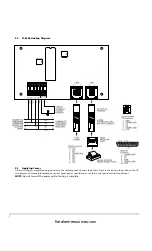
Wiring. . . . . . . . . . . . . . . . . . . . . . . . . . . . .1

3.4

PC4400 Hookup Diagram . . . . . . . . . . . .2

3.5

Applying Power . . . . . . . . . . . . . . . . . . . .2

4.

Enrolling the Module. . . . . . . . . . . . . . . . . . . . . .3

5.

Programming the Module. . . . . . . . . . . . . . . . . .3
5.1

Baud Rate . . . . . . . . . . . . . . . . . . . . . . . . . .3

5.2

DVAC Options  . . . . . . . . . . . . . . . . . . . . .3

5.3

DVAC Identifiers  . . . . . . . . . . . . . . . . . . .3

5.4

Default DVAC . . . . . . . . . . . . . . . . . . . . . .6

5.5

Trouble Conditions. . . . . . . . . . . . . . . . . .6

Programming Worksheets . . . . . . . . . . . . . . . 7

Baud Rate

. . . . . . . . . . . . . . . . . . . . . . . . . . . . . . . . . 7

DVAC Options  . . . . . . . . . . . . . . . . . . . . . . . . . . . . . . . .7
Default DVAC Programming

. . . . . . . . . . . . . . . . .   7

DVAC Identifiers

 . . . . . . . . . . . . . . . . . . . . . . . . . . . 8

Zone X Alarm/Restore. . . . . . . . . . . . . . . . . . . . . . . . . .8
DVAC Identifiers

 . . . . . . . . . . . . . . . . . . . . . . . . . . . 9

Zone X Trouble/Restore  . . . . . . . . . . . . . . . . . . . . . . . .9
Zone X Fault/Restore . . . . . . . . . . . . . . . . . . . . . . . . . .10
Module Tamper/Restore . . . . . . . . . . . . . . . . . . . . . . .11
Priority Alarms . . . . . . . . . . . . . . . . . . . . . . . . . . . . . . .11
Openings and Closings by User . . . . . . . . . . . . . . . . .12
Miscellaneous Openings and Closings  . . . . . . . . . . .13
Partition Openings and Closings . . . . . . . . . . . . . . . .13
System Maintenance. . . . . . . . . . . . . . . . . . . . . . . . . . .13
PC4204 Troubles . . . . . . . . . . . . . . . . . . . . . . . . . . . . . .13
Fire Module . . . . . . . . . . . . . . . . . . . . . . . . . . . . . . . . . .13
Wireless – Low Batter. . . . . . . . . . . . . . . . . . . . . . . . . .14
Wireless – Low Battery. . . . . . . . . . . . . . . . . . . . . . . . .14
Police Code (PC) . . . . . . . . . . . . . . . . . . . . . . . . . . . . . .14
DVAC Module. . . . . . . . . . . . . . . . . . . . . . . . . . . . . . . .14

DVAC Identifiers . . . . . . . . . . . . . . . . . . . . . . 15

Function Bytes . . . . . . . . . . . . . . . . . . . . . . . . . . . . . . . .15

Alarm Function Bytes  . . . . . . . . . . . . . . . . . . . .15
Trouble Function Bytes . . . . . . . . . . . . . . . . . . .15
Bypass Function Bytes . . . . . . . . . . . . . . . . . . . .16
Supervisory Function Bytes  . . . . . . . . . . . . . . .16
Opening and Closing Function Bytes . . . . . . .16
Miscellaneous Function Bytes  . . . . . . . . . . . . .17
7E/FE : Specific Message Function Byte. . . . .17

1.

Introduction

The PC4400 module adds serial printer or DVAC com-
munications capability to a MAXSYS PC4010 or PC4020
security system.

2.

Specifications

• Four wire (QUAD) hook-up to Combus
• Normal current draw of 35 mA
• Tamper and Trouble reporting codes
• Low Combus supervision to Main Control Panel
• Maximum cable length: 200 feet (61 meters)

PC4400 connected to a serial printer:

• True RS-232 technology
• Protocol XON/XOFF or DTR
• Five possible baud rates: 300, 600, 1200, 2400 or 4800

NOTE:

 4800 Baud only available on PC4010/PC4020

V2.1 and above.

PC4400 connected to a DVAC network:

• Automatic programming for DVAC function bytes and

reporting codes.

• Programmable response type to all calls
• Monitoring for DVAC Line fault
• Module self diagnostics

3.

Installing the PC4400

3.1

Unpacking

The PC4400 package includes the following parts:
• One PC4400 circuit board
• Four plastic stand-offs

3.2

Mounting the Cabinet

When mounting a new cabinet for the PC4400, select a
dry location close to either the serial printer or the F1/F2
subsets if DVAC communication is to be used.
To mount the cabinet:
1. From the back of the cabinet, press in the four white

circuit board stand-offs into the raised mounting
holes.

2. Holding the cabinet in position, pull all wiring into

the cabinet through the hole in the back.

3. Using the provided mounting screws and appropri-

ate wall anchors, mount the cabinet securely to the
wall.

4. Press the PC4400 module onto the plastic stand-offs.

3.3

Wiring

Before beginning to wire the unit, ensure that all power
(AC transformer and battery) is disconnected from the
control panel.
Perform the following steps to complete wiring:
1. Connect the four Combus wires to the PC4400. Con-

nect the red, black, yellow and green Combus wires
to the RED, BLK, YEL and GRN terminals, respec-
tively.

2. Connect terminals T1 and T2 to a normally closed

tamper switch. If no tamper switch is desired, con-
nect a jumper wire between T1 and T2 terminals.

Consult the wiring diagram on page 2 for further infor-
mation.

firealarmresources.com

Содержание MAXSYS PC4400

Страница 1: ...de WARNING This manual contains information on limitations regarding product use and function and information on the limitations as to liability of the manufacturer The entire manual should be carefully read firealarmresources com ...

Страница 2: ...ic Audible warning devices however loud may not be heard by a hearing impaired person Telephone Lines If telephone lines are used to transmit alarms they may be out of service or busy for certain periods of time Also an intruder may cut the telephone line or defeat its operation by more sophisticated means which may be difficult to detect Insufficient Time There may be circumstances when the syste...

Страница 3: ...g 7 DVAC Identifiers 8 Zone X Alarm Restore 8 DVAC Identifiers 9 Zone X Trouble Restore 9 Zone X Fault Restore 10 Module Tamper Restore 11 Priority Alarms 11 Openings and Closings by User 12 Miscellaneous Openings and Closings 13 Partition Openings and Closings 13 System Maintenance 13 PC4204 Troubles 13 Fire Module 13 Wireless Low Batter 14 Wireless Low Battery 14 Police Code PC 14 DVAC Module 14...

Страница 4: ...gth 200 feet 61 meters PC4400 connected to a serial printer True RS 232 technology Protocol XON XOFF or DTR Five possible baud rates 300 600 1200 2400 or 4800 NOTE 4800 Baud only available on PC4010 PC4020 V2 1 and above PC4400 connected to a DVAC network Automatic programming for DVAC function bytes and reporting codes Programmable response type to all calls Monitoring for DVAC Line fault Module ...

Страница 5: ... power to the control panel Connect the battery leads to the battery then connect the AC transformer For more information on control panel power specifications see the control panel Installation Manual NOTE Do not connect the power until all wiring is complete firealarmresources com ...

Страница 6: ...ule will use to communicate with a serial printer The baud rate is the speed at which information will be transmitted from the PC4400 module to the serial printer There are five different baud rates available to the PC4400 module 300 600 1200 2400 and 4800 baud If you are experiencing problems with miss ing characters try lowering the baud rate NOTE 4800 Baud only available on PC4010 PC4020 V2 1 a...

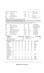
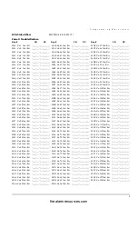
Страница 7: ... System AC Trouble Restore 3A BA 001 AC Cut 0264 System Bell Trouble Restore 32 B2 135 System trb 0265 System Aux Supply Trouble Restore 3C BC 001 PwSuply 0266 Combus Trouble Restore 32 B2 131 System trb 0267 0268 TLM Line 1 2 Trouble Restore 3E BE 001 002 Line 0269 FTC Restoral 00 Not Transmitted 026A System Periodic Test 00 Not Transmitted 026B Event Buffer 75 Full 32 132 System trb 026C System ...

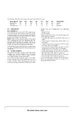
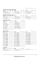
Страница 8: ...b Restore 3C BC 011 026 Not Transmitted 2EE 32D Wireless Zone Supervisory 18 98 151 214 Not Transmitted 338 DVAC Line Fault 3E BE 004 Not Transmitted 339 DVAC Module Fault 32 B2 137 Not Transmitted 33A DVAC Shut Down by C S 32 B2 138 Not Transmitted Zone Events PC4020 Event DVAC Printer MSG PC4020 Event DVAC Printer MSG Zone Alarm Alm Zone Trouble Tamper Restore T_R Zone Restore Rst Zone Fault Sup...

Страница 9: ...ns If a trouble condition occurs the keypad Trouble light will turn on and the keypad will beep Press 2 to display the trouble conditions The following trouble conditions apply to the PC4400 module For a description of all troubles please see your system Installation Manual Reporting codes for these troubles can be programmed ref 000403 OR scroll to System Area then Communicator then Reporting Cod...

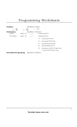
Страница 10: ...t FF I_______I________I Valid entries 01 FF All Call Select Default FF I_______I________I Valid entries 00 04 00 no response to all calls 01 response to all call 1 only 02 response to all call 2 only 03 response to both all calls 04 response to all call 1 if ID code is odd or to all call 2 if ID code is even Default DVAC Programming REFERENCE 00080102 firealarmresources com ...

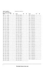
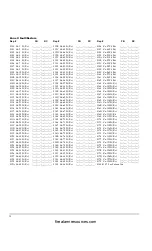
Страница 11: ...003E Zn 63 Alm Rst I_______I________I I_______I________I_______I 003F Zn 64 Alm Rst I_______I________I I_______I________I_______I 0040 Zn 65 Alm Rst I_______I________I I_______I________I_______I 0041 Zn 66 Alm Rst I_______I________I I_______I________I_______I 0042 Zn 67 Alm Rst I_______I________I I_______I________I_______I 0043 Zn 68 Alm Rst I_______I________I I_______I________I_______I 0044 Zn 69...

Страница 12: ... 00BE Zn 63 Trb Rst I_______I________I I_______I________I_______I 00BF Zn 64 Trb Rst I_______I________I I_______I________I_______I 00C0 Zn 65 Trb Rst I_______I________I I_______I________I_______I 00C1 Zn 66 Trb Rst I_______I________I I_______I________I_______I 00C2 Zn 67 Trb Rst I_______I________I I_______I________I_______I 00C3 Zn 68 Trb Rst I_______I________I I_______I________I_______I 00C4 Zn 6...

Страница 13: ..._______I I_______I________I_______I 013F Zn 64 Ft Rst I_______I________I I_______I________I_______I 0140 Zn 65 Ft Rst I_______I________I I_______I________I_______I 0141 Zn 66 Ft Rst I_______I________I I_______I________I_______I 0142 Zn 67 Ft Rst I_______I________I I_______I________I_______I 0143 Zn 68 Ft Rst I_______I________I I_______I________I_______I 0144 Zn 69 Ft Rst I_______I________I I______...

Страница 14: ...__ ______I I_______I________I_______I 01A5 PC41XXMd13 I_______I__ ______I I_______I________I_______I 01A6 PC41XXMd14 I_______I__ ______I I_______I________I_______I 01A7 01A8 For Future Use 01A9 PC4216Md1 I_______I________I I_______I________I_______I 01AA PC4216Md2 I_______I________I I_______I________I_______I 01AB PC4216Md3 I_______I________I I_______I________I_______I 01AC PC4216Md4 I_______I____...

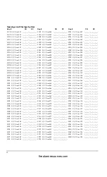
Страница 15: ...C User 063 I_______I________I I_______I________I_______I 020D O C User 064 I_______I________I I_______I________I_______I 020E O C User 065 I_______I________I I_______I________I_______I 020F O C User 066 I_______I________I I_______I________I_______I 0210 O C User 067 I_______I________I I_______I________I_______I 0211 O C User 068 I_______I________I I_______I________I_______I 0212 O C User 069 I____...

Страница 16: ..._____I_______I 027E Batt TrbMd3 I_______I________I I_______I________I_______I 027F AC TrbMd3 I_______I________I I_______I________I_______I 0280 AUX SupMd3 I_______I________I I_______I________I_______I 0281 Batt TrbMd4 I_______I________I I_______I________I_______I 0282 AC TrbMd4 I_______I________I I_______I________I_______I 0283 AUX SupMd4 I_______I________I I_______I________I_______I 0284 Batt Trb...

Страница 17: ...____I I_______I________I_______I 02F2 Zn 05 superv I_______I________I I_______I________I_______I 02F3 Zn 06 superv I_______I________I I_______I________I_______I 02F4 Zn 07 superv I_______I________I I_______I________I_______I 02F5 Zn 08 superv I_______I________I I_______I________I_______I 02F6 Zn 09 superv I_______I________I I_______I________I_______I 02F7 Zn 10 superv I_______I________I I_______I_...

Страница 18: ...9 1F 9F Cancel OC OC 000 999 The zone number of each alarm and restoral will also be printed in the form of Alm Rst Zn000 999 Trouble Function Bytes In the following list there are two entries for each event in the Function Byte column The first number corresponds to a trou ble the second corresponds to the trouble restoral Each event will thus be printed in one of two ways For example 26 Burglar ...

Страница 19: ...there are two entries for each event in the Function Byte column The first number corresponds a supervi sory the second corresponds to a supervisory restoral Each event will thus be printed in one of two ways For example 66 Burglar Sup Zn001 BS 001 This event is a supervisory E6 Burglar S_R Zn001 BJ 001 This event is an supervisory restore Function Byte Printer Message Computer Message Function By...

Страница 20: ...019 Access Denied DD 020 Access Granted DG 021 Access Lockout DK 022 Access Open DO 023 Access Trouble DT 024 Door Forced DF Zn Printer MSG Computer MSG 025 Door Station DS 026 Alm On Exit UA 027 Fire test begin FI 028 Fire test end FK 029 User cd Tamper JA 030 Log Threshold JL 031 Log Overflow JO 032 Schedul Execute JR 033 Schedul Change JS 034 Time Changed JT 035 Date Changed JD 036 Holiday Chan...

Страница 21: ... 2001 Digital Security Controls Ltd Toronto Canada www dsc com 1 800 387 3630 Printed in Canada 29002039 R003 firealarmresources com ...

Отзывы: