English
I NS TAL L ATI O N MA N U A L
!Caution
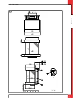
Between the plate material and the construction frame, the insulation tape must be glued on the appliance;
plate material may not get into contact with the appliance (see Appendix 3, fig. 4b, arrow 1).
Ø
Apply the ventilation holes at both sides of the chimney breast.
Ø
Attach the air supply to the bottom of the chimney breast: min. 32x335 mm (see Appendix 3, fig. 4a, arrow 1).
Ø
When using plaster finishing, the chimney breast should dry for at least 6 weeks before it is taken into operation,
in order to prevent cracks.
5.6 Connecting gas
Use the following procedure when connecting the gas; see also section 5.2, Gas connection:
!Caution
-
The gas control is located under the appliance;
-
Prevent twisting the gas tap when connecting the gas pipe.
Ø
If necessary, blow clean the gas pipe.
Ø
Connect the gas pipe with gas tap to the gas control.
Ø
Bleed the gas pipe.
5.7 Adjusting the appliance
The appliance has to be set in such a way that it works correctly in combination with the applied concentric
system.
For that purpose you may want to place a restrictor slide or remove the air inlet guide. The conditions for using a
wall terminal are described in section 5.4.2.1, and for using a roof terminal in section 5.4.3.1.
5.7.1 Restrictor slide (R)
The Restrictor slide (R) is supplied separately (see Appendix 3, fig. 5a).
This is mounted as follows (see Appendix 3, fig. 5b):
Ø
Place the Restrictor slide.
Ø
Use the template supplied to set the distance of the restriction (see Appendix 3, fig. 5c) as follows:
-
A distance of 5 mm means that the Restrictor slide is closed to a maximum level;
-
A distance of 9 and 14 mm is set by means of the template.
Ø
Fix the Restrictor slide by using the self-tapping screw (U).
5.7.2 Air inlet guide
5.7.2.1 Removing the air inlet guide (L)
The air inlet guide (L) is fixed to the back wall at the bottom of the appliance. You can see it if you look across the
burners.
If you want to remove it, proceed as follows (see Appendix 3, fig. 6a):
Ø
Unscrew the self-tapping screws (N) using the socket spanner supplied with the appliance and remove them.
Ø
Remove the air inlet guide.
Ø
Retighten the self-tapping screws (N).
UK
Содержание G20
Страница 28: ...E n g l i s h INSTALLATION MANUAL UK A C B C 38c 1461 A B 38c 1 462 3a 2 3b 3c ...
Страница 31: ...E n g l i s h INSTALLATION MANUAL UK L N 38c 1467 38p 0022 38p 0023 38p 0028 38p 0036 8 6 9 7a 7b ...
Страница 32: ...E n g l i s h INSTALLATION MANUAL UK E 38p 0029 A B C D A 38p 0030 B 38p 0031 10a 10b 10c ...
Страница 33: ...E n g l i s h INSTALLATION MANUAL UK C 38p 0032 D 38p 0033 E 38p 0034 10d 10e 10f ...
Страница 34: ...E n g l i s h INSTALLATION MANUAL UK 38p 0035 38p 0062 10g 10h ...
Страница 36: ...E n g l i s h INSTALLATION MANUAL UK 38p 0061 38c 1472 A 38p 0038 A B 38p 0037 38p 0179 12 12a 12b 13 14 15 ...
Страница 37: ...E n g l i s h INSTALLATION MANUAL UK 38p 0181 5mV 38p 0182 20mm 25mm 38c 1471 1 16 17 18 ...
Страница 38: ...E n g l i s h INSTALLATION MANUAL UK ...
Страница 39: ...E n g l i s h INSTALLATION MANUAL UK ...
Страница 40: ...E n g l i s h DRU Verwarming B V The Netherlands Postbus 1021 NL 6920 BA Duiven Ratio 8 NL 6921 RW Duiven UK ...


