background image

English

I NS TAL LAT ION M ANUA L

UK

Country

NL / DK / FI / NO / SE / HU / BA / GR

FR / BE / IT / PT / ES / GB / IE

DE

mbar

30

37

50

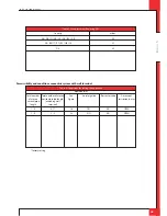
Table 3: Line-pressure when using G31

Total number

of meters

vertical pipe

length

1 - 4

1 - 4

Total number of meters

horizontal pipe length

(excluding wall

terminal)

0 - 1*

2 - 5

Table 4: Conditions for setting the appliance

See

Figure

3b

3c

Air inlet guide

YES

NO

Restrictor slide

NO

NO

Distance of

restriction in mm

OPEN

OPEN

* factory setting

Permissibility and conditions concentric system with wall terminal

G20/G25/G31

Содержание G20

Страница 1: ...E n g l i s h Store this document in a safe place Milo Small Installation manual GB IE DRU46686 184218 EN 0713 3 G20 G25 Natural gas G31 Propane UK 959 030 04 UK ...

Страница 2: ... 1 Placing the narrow chimney brest 5 6 Connecting gas 5 7 Adjusting the appliance 5 7 1 Restrictor slide 5 7 2 Air inlet guide 5 7 2 1 Removing the air inlet guide 5 8 Placing the wood set 5 9 Glass panes 5 9 1 Front glass pane 5 9 1 1 Removing the front glass pane 5 9 1 2 Placing the front glass pane 5 9 2 Side glass panes 5 9 2 1 Removing the side glass pane 5 9 2 2 Placing the side glass pane ...

Страница 3: ...U Powervent system the DRU Smartvent system or the DRU Maxvent system you must carefully and fully read and use the accompanying installation manual as well prior to its installation The following symbols are used in the manual to indicate important information Ø Work to be performed Tip Suggestions and recommendations Caution You will need these instructions to prevent problems that might occur d...

Страница 4: ...ystems supplied by DRU Ø if you are installing a free standing appliance place the appliance away from the back wall by the minimum distance stated further down in the text Ø do not cover the appliance and or do not wrap it in an insulation blanket or any other material Ø make sure that combustible objects and or materials have a distance from the appliance of at least 500 mm Ø only use the accomp...

Страница 5: ...fix the appliance to a platform or pallet Caution Heat resistant glass is a ceramic material Very small irregularities in the glass pane s cannot be avoided but are within the required quality standards Caution Keep plastic bags away from children In Appendix 2 Table 1 you can see which parts you should have after removing the packaging Ø Contact your supplier if you do not have all the parts afte...

Страница 6: ...becoming too high including the materials and or objects behind the wall Comply with the minimum required free space of 500 mm at both sides of the appliance as well as above the appliance because of the heat emission of the appliance Make sure that combustible objects and or materials have a distance from the appliance of at least 500 mm Do not suspend the appliance too close to the wall this is ...

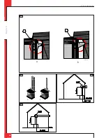
Страница 7: ...dix 3 fig 3a The passage to the outside can be made with a wall terminal see section 5 4 2 or a roof terminal see section 5 4 3 If necessary you can also use an existing chimney see section 5 4 4 Caution Only use the rectangular and or round concentric system supplied by DRU This system has been tested together with the appliance DRU cannot guarantee a proper and safe operation of other systems an...

Страница 8: ... is mounted on the intermediate plate Caution When using rectangular pipes it is only possible to end in the wall from which the appliance is suspended there is no bend available for the concentric system When the pipes end at right angles in the appliance you can start with rectangular pipes but you must change over to the round system Some heat resistant insulation materials contain volatile com...

Страница 9: ...he procedure described below First a concentric pipe of at least 1 meter should be connected vertically to the appliance Depending on the construction of the concentric system the appliance is set by placing the Restrictor slide and or removing the air inlet guide In the following procedure you can see how the allowability of a concentric system can be determined and which settings are needed Ø De...

Страница 10: ...lace the coupling piece on the flue spigot Secure the coupling peace at both front sides using 2 self tapping screws Place a red seal on the coupling piece Then place a rectangular pipe piece or an adapter to round Secure the rectangular pipe piece or adapter at both front sides using 2 self tapping screws At each next rectangular pipe piece or at the adapter place the spacer brackets on the pipe ...

Страница 11: ...cluding the top of the chimney breast the material in the chimney breast and the back wall of the chimney breast The ventilation holes which at both sides should be mounted as high as possible should have a combined passage of at least 200 cm2 Make an air supply at the bottom of the chimney breast Protect the gas control and pipes against cement and plaster Protect the receiver against dust and mo...

Страница 12: ... correctly in combination with the applied concentric system For that purpose you may want to place a restrictor slide or remove the air inlet guide The conditions for using a wall terminal are described in section 5 4 2 1 and for using a roof terminal in section 5 4 3 1 5 7 1 Restrictor slide R The Restrictor slide R is supplied separately see Appendix 3 fig 5a This is mounted as follows see Appe...

Страница 13: ... fig 10b up to 10h Caution The logs should not completely cover the burner openings the logs are placed correctly if the positioning ridges have been used If necessary improve the placement of the logs Ø Spread the glow material evenly over the burner Tip Fasten the glow material under chips and or wood set Ø Finally place the chips around the logs see Appendix 3 fig 10g circle fig 10h for propane...

Страница 14: ...e see section 5 9 1 1 above Ø Loosen the bolts of the lower and upper glass strip by 2 strokes using the socket spanner supplied Ø Remove the glass pane by sliding it towards the front and out of the clamp Ø Store the glass pane on a safe place 5 9 2 2 Placing the side glass pane Placing the side glass pane will take place in reverse order of the removal procedure described above Caution Apply suf...

Страница 15: ... antenna in order to avoid damaging the receiver Avoid formation of dust on or in the receiver cover it when performing work Place the receiver in its intended holder under the appliance or in the control hatch according to Appendix 3 fig 14 If you want to use an adapter only an adapter supplied by DRU will guarantee a proper operation of the receiver 6 1 1 Placing replacing the receiver s batteri...

Страница 16: ... the pilot flame does not ignite repeat the ignition procedure until the pilot burner ignites consult the malfunction search diagram Appendix 1 if this does not happen after a few attempts Ø After igniting the pilot flame the main burner will ignite during the ignition procedure Ø Check whether the main burner continues to burn Ø If the main burner does not continue to burn repeat the ignition pro...

Страница 17: ...the glass window is installed Use the malfunction search diagram Appendix 1 if the ignition of the main burner does not comply with the abovementioned requirements 7 4 Flame picture The flame picture can only really be assessed when the appliance has been burning for several hours Volatile components from paint materials etc which evaporate in the first hours will affect the flame picture Caution ...

Страница 18: ...ponents the pilot burner malfunction search diagram Appendix 1 the space surrounding the pilot burner the glass pane s Caution Remove place the glass pane s as described in section 5 9 Remove the deposit on the inside of the glass pane s with a damp cloth or a non abrasive detergent such as copper polish or a ceramic hot plate cleaner Avoid remove fingerprints on the glass pane s since otherwise t...

Страница 19: ...or openers Ø Instruct the user about the appliance and the remote control Ø When the appliance is started for the first time point out that In order to avoid cracks in a chimney breast made of stone like materials or finished with plaster it should dry for at least 6 weeks prior to putting the appliance into operation When the appliance is stoked up for the first time volatile components evaporate...

Страница 20: ...nded tip bend tip 1 mm higher Spark too weak thin and reddish Act as if no spark in box 2 05 and perform actions described for ignition cable and ignition electrode Pilot flame too weak dirty Remove injector remove gland nut and the pilot tube See that it does not fall away Clean with compressed air Rectify Retry 2 05 Check Ignition cable Present and connected Being free from metal parts or concre...

Страница 21: ...evenly distributed across burner s chips on burner lack of combustion air See 2 15 cross lighting in low setting possible when thermostat function is used 2 15 Check Gas supply Supply pressure does not drop away as main burner or other appliance lights causing pilot flame to shorten Burner pressure too high or too low Flames instable suffocating lack of air Dancing flames on burner Lack of combust...

Страница 22: ...flame low button on remote within 20 seconds Then 2 short beeps and brief noise of servomotor to confirm that communication code was set succesfully Remote control Battery 9V empty see indication on display Several After switching off going out the remote set is locked for 120 sec older versions 60 sec Wait 2 minutes before reigniting 1 04 Check All appliances 8 wire cable between receiver and gas...

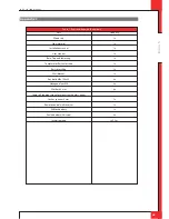
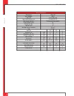
Страница 23: ...or slide Restrictor slide Wall bracket Key bolts M8x 140x50 Hexagonal nut M8 Washer 8 4 mm Spare self tapping screws for mounting the glass panes Socket spanner 8 mm Remote control with receiver 9V block battery Penlite battery AA type Insulation tape Quantity 1x 1x 1x 1x 1x 1x 1x 1x 4x 4x 4x 1x 1x 1x 4x 2x 0 5 m Table 1 Parts included with the delivery ...

Страница 24: ...ner pressure Nominal heat input Hs Nominal heat input Hi Nominal output Consumption Burner injector Consumption on low output Low setting injector Pilot burner injector Efficiency class Milo Small Built in Closed combustion Concentric 200 130 Pilot flame with thermocouple Yes No Yes 200 cm2 C11 C31 mbar kW kW kW L h mm L h mm Code G20 15 4 6 6 6 5 1 623 Ø 1 95 370 Ø 1 6 51 1 G25 19 6 1 5 5 4 6 658...

Страница 25: ...of meters vertical pipe length 1 4 1 4 Total number of meters horizontal pipe length excluding wall terminal 0 1 2 5 Table 4 Conditions for setting the appliance See Figure 3b 3c Air inlet guide YES NO Restrictor slide NO NO Distance of restriction in mm OPEN OPEN factory setting Permissibility and conditions concentric system with wall terminal G20 G25 G31 ...

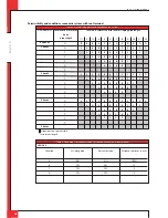
Страница 26: ...5 Determining permissibility concentric system G20 G25 G31 Total number of meters horiz pipe length Total no of meters vertical and or sloping pipe length no bends 2 bends 3 bends 4 bends 5 bends Situation is not permissible minimum length Situation A B C D Air inlet guide NO YES YES YES Table 6 Conditions for the adjustment of the appliance with a roof terminal Restrictor slide NO YES YES YES Dis...

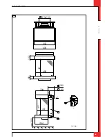
Страница 27: ...E n g l i s h INSTALLATION MANUAL UK 80 102 451 480 310x100 550 605 180 230 334 451 362 301 min 250 A 2 3 A 1 38C 1460 1 1 ...

Страница 28: ...E n g l i s h INSTALLATION MANUAL UK A C B C 38c 1461 A B 38c 1 462 3a 2 3b 3c ...

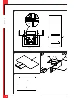
Страница 29: ... g l i s h INSTALLATION MANUAL UK 38c 1428 64 335 500 600 490 542 32 72 114 582 664 180 230 Min 800 min 15 max 30 Min 200 cm 38c 1463 1 335 490 32 664 180 230 Min800 min 15 max 30 Min 200 cm 1 B mm A 4a 3d ...

Страница 30: ...E n g l i s h INSTALLATION MANUAL UK A A SECTION A A 2 mm 1 38c 1464 R 38c 1466 U R 38c 1468 9 14 38c 1469 5a 4b 5b 5c ...

Страница 31: ...E n g l i s h INSTALLATION MANUAL UK L N 38c 1467 38p 0022 38p 0023 38p 0028 38p 0036 8 6 9 7a 7b ...

Страница 32: ...E n g l i s h INSTALLATION MANUAL UK E 38p 0029 A B C D A 38p 0030 B 38p 0031 10a 10b 10c ...

Страница 33: ...E n g l i s h INSTALLATION MANUAL UK C 38p 0032 D 38p 0033 E 38p 0034 10d 10e 10f ...

Страница 34: ...E n g l i s h INSTALLATION MANUAL UK 38p 0035 38p 0062 10g 10h ...

Страница 35: ...E n g l i s h INSTALLATION MANUAL UK 38p 0041 38p 0039 38p 0040 38p 0042 38p 0043 38p 0044 38p 0060 11c 11a 11b 11f 11d 11e 11g ...

Страница 36: ...E n g l i s h INSTALLATION MANUAL UK 38p 0061 38c 1472 A 38p 0038 A B 38p 0037 38p 0179 12 12a 12b 13 14 15 ...

Страница 37: ...E n g l i s h INSTALLATION MANUAL UK 38p 0181 5mV 38p 0182 20mm 25mm 38c 1471 1 16 17 18 ...

Страница 38: ...E n g l i s h INSTALLATION MANUAL UK ...

Страница 39: ...E n g l i s h INSTALLATION MANUAL UK ...

Страница 40: ...E n g l i s h DRU Verwarming B V The Netherlands Postbus 1021 NL 6920 BA Duiven Ratio 8 NL 6921 RW Duiven UK ...

Отзывы: