


10
Instructions for use NIMBO
Drive Medical GmbH & Co. KG | As per: 10.07.2020 | Errors and alterations excepted
EN
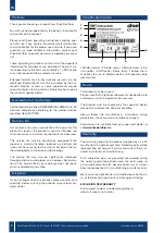
Safety instructions
• Read these instructions for use carefully.
• All components should be checked for damage and a
secure fit prior to use. Do not use product if there are
any defects!
• Use the product only as a walking aid!
• Use the product only on an even and solid surface.
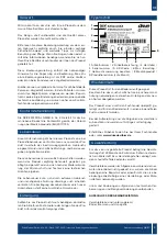
• Take note of the permitted maximum weight of the user.
This information can be found in the technical data in
these instructions for use as well as on the identifica-
tion plate.
• Use on escalators and the like is expressly prohibited!
• Do not hang any bags on the handle – risk of tipping!
• When folding and unfolding the product, clothing and
body parts can be pinched.
• Protect the product from direct sunlight. Product parts
can become hot and cause skin injuries if touched.
• Prior to each use, ensure that your product is intact and
all adjustable parts are properly secured.
• Check the screws on the product regularly and tigh-
ten, if necessary.
• The correct use of the product requires accurate and
careful training of the caregiver.
• Users who have difficulty reading must have the ins-
tructions for use read to them in order to understand
how to handle the product.
• For indoor use only!
• Use only under supervision.
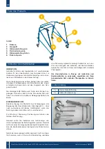
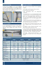
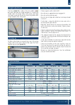
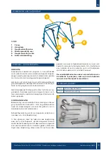
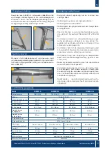
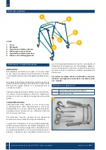
Preparing for use
The Nimbo has a folding alu-
minum tubular frame and is
also height-adjustable at the
wheels. To unfold it, lay the
Nimbo on the ground, hold it
approximately in the center of
the front frame and unfold the
frame. When unfolding it, be
aware that the spring clips in
the telescopic tubes must al-
ways properly click into place
(audible click)
(photo 2)
.
For assembly, only the front and rear wheels need to be
inserted.
3
4
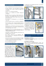
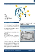
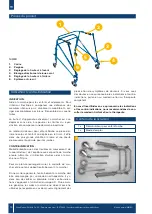
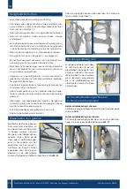
Front wheel lock
To lock the front wheels,
straighten the wheels (
1
), then
pull the locking pin upwards
(
2
) and rotate it 90° (
3
) until it
clicks into place in the hinged
plate (
4
). To release the wheel
lock, repeat the procedure.
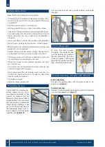
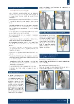
Enable backstop | Disable rear wheels
Enable backstop
Connect the locking lever with the gear wheel at the
wheel axle (
photo 6
).
Disable backstop
Release the locking lever once again and push it upwards
into the intended mount (
photo 7
).
6
7
2
5


