11
ULTRA-SORB MODEL XV INSTALLATION, OPERATION, AND MAINTENANCE MANUAL
Notes:
1. Dashed lines indicate provided by installer.
2. See Figures 12-1 and 12-2 for trap clearance alternatives.
3. Steam supply line to unit and piping are not included.
4. Dispersion tubes are available on 3", 4", 6", 9" and 12" (76, 102 152, 229, and 305 mm)
centers.
5. Ultra-sorb steam dispersion panels will be assembled, crated, and shipped intact in all sizes
up to 98" (2490 mm) overall height. Any Ultra-sorb can be shipped unassembled by request,
requiring fi eld assembly.
6. Standard sizes are 12" x 12" up to 144" x 144" in 1" increments (305 x 305 mm up to 3660
x 3660 mm in 25 mm increments).
Larger sizes are available.
7. Heat exchanger requires 5 psig (35 kPa) minimum steam pressure.
Mounting in an air handling unit
• Metal support frames should be anchored to the air handler casing.
• Drill or screw through the header assembly only where shown in Figure 10-1. Screws and drill
bits must not penetrate more than 3/4" (20 mm) into the header assembly.
• Use 1/4–20 nuts and bolts or #12 self drilling and tapping screws.
• Fastener spacing should not to exceed 6" (150 mm).
• When Ultra-sorb Model XV is installed in bypass air applications provide additional bracing for
the unsupported side(s).
• Install the panel level. If slope cannot be avoided, ensure that the slope is toward the drain end
of the panel.
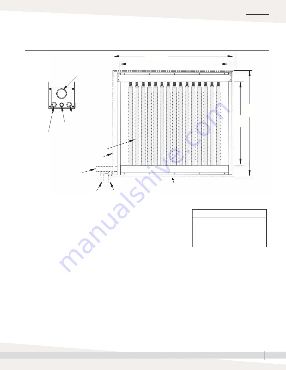
Connection end
of header
Humidifi cation steam
inlet:
• 1" or 2" NPT
(DN25 or DN50),
determined by
maximum steam
capacity
• 3" (DN80) fl ange,
STS humidifi er
connection only
Pressurized boiler steam inlet
(3/4" NPT, internal thread)
Pressurized condensate outlet
(3/4" NPT, internal thread)
Float switch, optional header overfl ow/
access port (1/2" NPT, internal thread)
Tubelets perpendicular to airfl ow
Humidifi cation steam to header
AHU wall
Pressurized
condensate out to
return main
Steam from pressurized steam
source to heat exchanger
Header
CAUTION
Use a backup wrench
Use a backup wrench on all
plumbing connections. Failure to
use a backup wrench could cause
damage to the Ultra-sorb Model XV.
INSTALLATION
Mounting in an air handler
Installation drawings:
FIGURE 11-1: ULTRA-SORB MODEL XV IN AN AIR HANDLER (HORIZONTAL AIRFLOW ONLY)
OM-7657a
Coil
height
AHU
height
Coil width
AHU width
Add center support required for all units
greater than 60" (1524 mm) wide.


