-
16
-
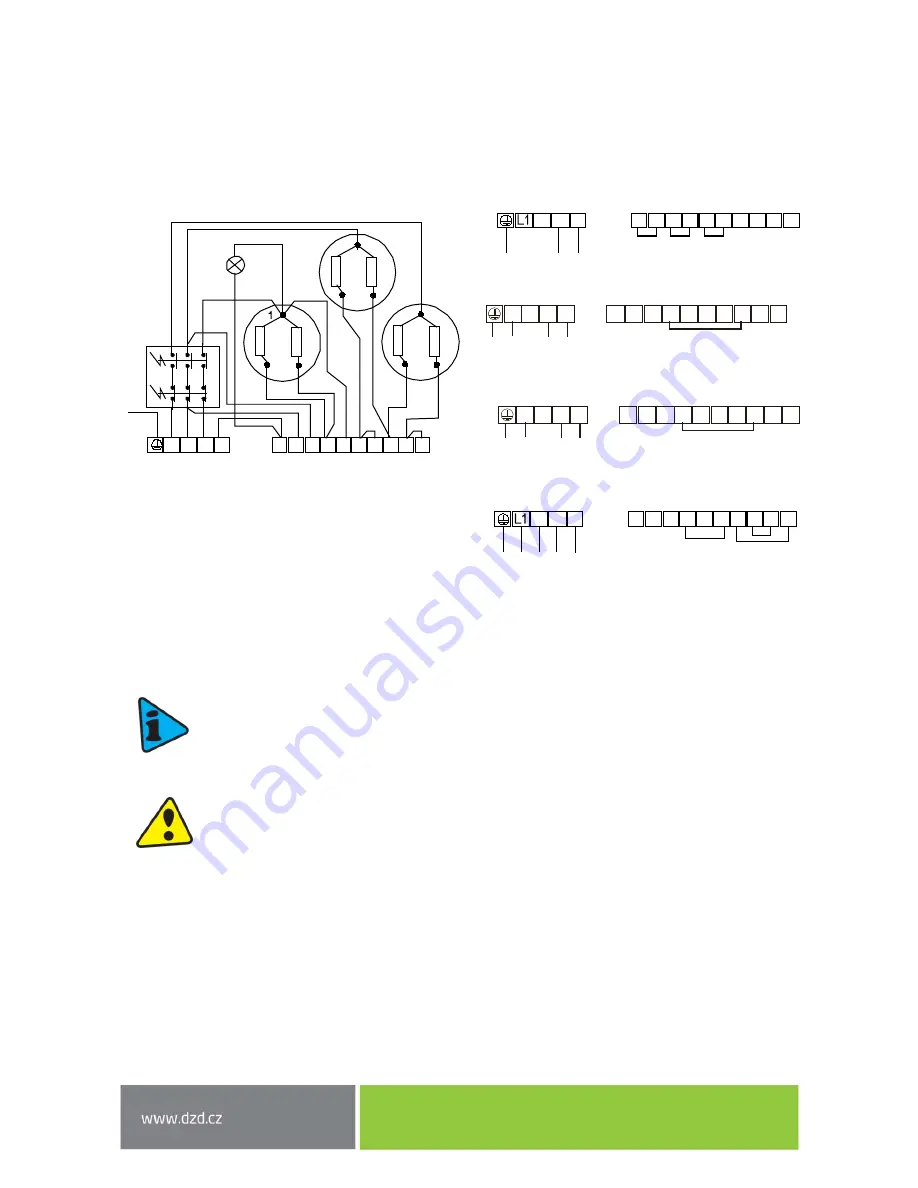
Heating unit 3-6 kW
The 3
-
6 kW heating unit allows 4 universal types of connection based on either the required time of
heating, or possibilities of electric network in the place of use. To achieve the chosen performance of the
heating unit, connect the inlet conductor to the terminal board L1
-L2-L3-
N and interconnect the terminals
on the terminal board 1
–
10 according to the below schemes:
R = 1 kW
3 kW
1 PE - N AC 230 V / 50 Hz
3 kW 2 PE - N AC 400 V / 50 Hz
4 kW
3 PE - N AC 400 V / 50 Hz
6 kW
3 PE - N AC 400 V / 50 Hz
2.3
PLUMBING FIXTURE
Power water connects to pipes with 3/4“.Blue
–
cold water supply, red
–
hot water outlet.
For potential disconnection of the heater, the service water inlets and outlets must be
provided with screw coupling Js 3/4“.The safety valve is mounted on the cold water inlet
identified with a blue ring.
Each hot service water pressure heater must have a membrane spring loaded with a safety
valve. Nominal clearance of safety valves is defined by standard.
The safety valve must be
easily accessible, as close to the heater as possible. The inlet pipes must have at least the
same clearance as the safety valve. The safety valve is placed high enough to secure dripping
water drain by gravity. We recommend mounting the safety valve onto a branch pipe. This
allows easier exchange without having to drain the water from the heater. Safety valves with
fixed pressure settings from the manufacturer are used for the assembly. Starting pressure
of a safety valve must be identical to the maximum allowed heater pressure and at least 20
% higher than the maximum pressure in the water main
(Table
6
). If the water main pressure
exceeds such value, a reduction valve must be added to the system.
. No stop valves can be
put between the heater and the safety valve.
During the assembly, follow the guide
provided by the safety equipment manufacturer.
1
1
2
2
2
3
3
3
R
R
R
R
R
R
L1 L2 L3
1 2 3 4 5 6 7 8
N
9 10
PE
L2 L3
1 2 3 4 5 6 7 8
N
9 10
L2 L3
1 2 3 4 5 6 7 8
N
9 10
L1 L2 L3
1
2
3
4
5
6
7
8
N
9
10
L1 L2 L3
1
2
3
4
5
6
7
8
N
9
10
Содержание OKC 160 NTR / BP
Страница 7: ... 7 OKCE 300 NTR 2 2 kW OKCE 300 NTR 3 6 kW OKC 300 NTR BP Figure 3 ...
Страница 8: ... 8 OKCE 300 NTRR 2 2 kW OKCE 300 NTRR 3 6 kW OKC 300 NTRR BP Figure 4 ...
Страница 20: ... 20 OKC 160 300 NTR Heated by a gas boiler with two pumps Figure 11 ...
Страница 21: ... 21 OKC 200 300 NTRR Heated by a gas boiler and solar collectors controlled by a three way valve Figure 12 ...


