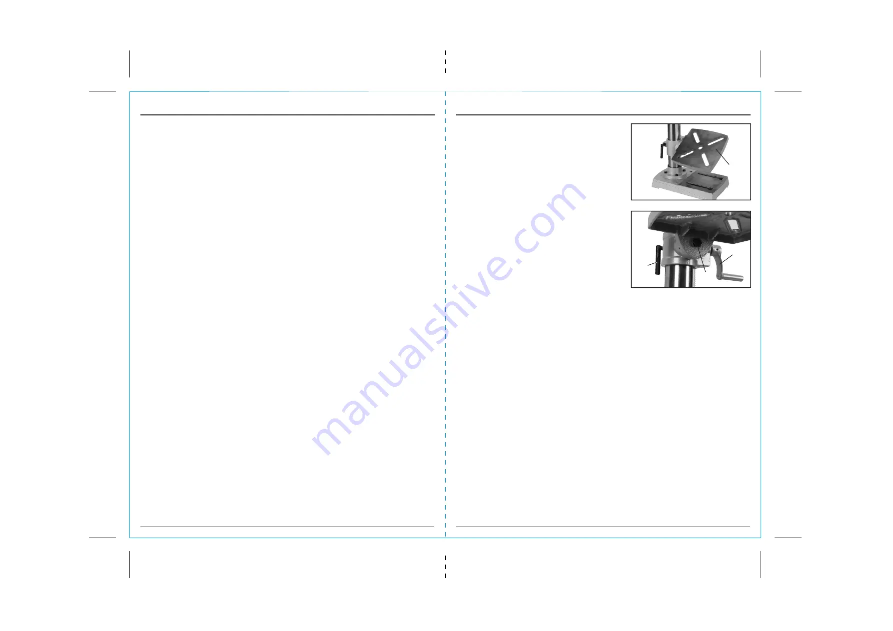
Draper 94803 Скачать руководство пользователя страница 8

FIG.13

FIG.14

9. SETTING 

THE 

DRILL

5.2 ADDITIONAL SAFETY INSTRUCTIONS FOR DRILLS

MECHANICAL HAZARDS:

1. 

Crushing. 

When setting/changing a tool or maintaining the machine avoid crushing injuries 

sustained between fixed and moving elements of the machine.

2. 

Cutting or Severing. 

At all times the workpiece shall be clamped as manual support will lead  

to injury.

3. 

Entanglement. 

Switch off the machine for maintenance, workpiece loading/unloading, swarf/chip 

removal, cutting/lubrication fluid application as contact with rotating spindle or tool will cause 
entanglement and possibly lead to injury and entrapment.

4. 

Impact. 

Ensure the workpiece is securely clamped at all times to avoid sudden movement 

(rotation) or ejection causing injury. Ensure any special tools associated with tool exchange, i.e. 
chuck key are removed prior to attempting to start the machine.

5. 

Stabbing, Cutting or Puncture Wounds. 

Take care when handling the tools and avoid contact 

with swarf and burrs created during drilling as they are extremely sharp.

ELECTRICAL HAZARDS:

1. 

Contact with Live parts. 

During commissioning, maintenance and trouble shooting operations 

do not remove, open or expose any electrical, terminal and control boxes due to the danger of 
electrocution. If the main cable is damaged, unplug the machine immediately and have the cable 
replaced before continuing.

AUDIBLE HAZARDS:

1. 

Hearing Loss. 

Wear ear defenders during operation to avoid damage to hearing, however ensure 

this does not interfere with speech communications or audible warnings.

MATERIAL HAZARDS:

1. 

Contact and Inhalation. 

Wear personal protective equipment to avoid contact from harmful 

fluids, gases or dust thrown or created during the drilling process.

2. 

Fire or Explosion. 

Do not drill or drill in the vicinity of flammable or combustible materials.

LOCATION:

1. 

Posture. 

Ensure when mounting the machine that the chosen location does not lead to unhealthy 

posture or repetitive strain during normal operation.

2. 

Lighting. 

Adequate lighting must be provided to ensure no operations are light impaired possibly 

leading to injury.

3. 

Reach. 

Do not reach over or around the machine at any time.

UNEXPECTED START-UP:

1. 

Remove the plug. 

Remove the plug from the socket before carrying out adjustment, servicing  

or maintenance.

ERRORS OF FITTING:

1. 

Tools. 

Ensure a suitable tool for the job in hand is securely and correctly fitted prior to starting the 

machine. Guards shall be fitted and in place at all times.

STABILITY:

1. 

Toppling. 

The drill shall be securely bolted down to a suitable and level surface to prevent the 

machine from overturning leading to injury.

2. 

Slipping. 

Ensure the area is clean of any residue cutting/lubrication fluid and other materials 

which may lead to a slip, trip or other such hazard.

5.  HEALTH AND SAFETY INFORMATION

- 8 -

- 17 -

9.4  WORK TABLE ADJUSTMENT -  

FIGS. 13 - 14

For versatility, the work table 

5

 can be raised or 

lowered, tilted ±45° or rotated 360° around the column.

 To tilt the table, loosen the 18mm bolt 

6

 Adjust the table’s degree of tilt and re-secure with 

locking bolt 

6

. Use the scale as a guide. 

Alternatively use a protractor off the table to the drill bit 
for more accuracy.

 To raise/lower the table working height, loosen locking 

handle 

7

 and turn the height adjustment crank 

handle 

8

 to raise or lower the table. Alternatively 

while locking handle 

7

 is loose the table can be 

rotated 180° to further increase the distance between 
the chuck and workpiece. When the adjustments are 
complete re-secure locking handle 

7

.

 The slots in the work table and base can 

accommodate locking bolts to secure a small vice 
enabling safe clamping of the workpiece.

CAUTION:

 A drill bit snagging on a piece of work will 

violently grab the piece of material, whipping it round 
and is likely to result in personal injury. Always ensure 
the workpiece is securely clamped.

5

7

8

6

Содержание 94803

Страница 1: ...ument is part of the product keep it for the life of the product passing it on to any subsequent holder of the product Read all these instructions before assembling operating or maintaining this product This manual has been compiled by Draper Tools describing the purpose for which the product has been designed and contains all the necessary information to ensure its correct and safe use By followi...

Страница 2: ... Tools Limited Permission is granted to reproduce this publication for personal and educational use only Commercial copying redistribution hiring or lending is prohibited No part of this publication may be stored in a retrieval system or transmitted in any other form or means without written permission from Draper Tools Limited In all cases this copyright notice must remain intact 1 2 REVISIONS Da...

Страница 3: ...STOCK 13 8 4 PLUNGE HANDLES 13 8 5 CHUCK 13 8 6 CHUCK GUARD 14 8 7 BENCH FLOOR MOUNTING 14 9 SETTING THE DRILL 9 1 SPINDLE SPEED ADJUSTMENT 15 9 2 BRILL BIT INSTALLATION REPLACEMENT 16 9 3 NO VOLT SWITCH 16 9 4 WORK TABLE ADJUSTMENT 17 9 5 GENERAL DRILLING 18 9 6 DUST AND SWARF 18 10 TROUBLESHOOTING 10 1 TROUBLESHOOTING 19 11 MAINTENANCE 11 1 MAINTENANCE 20 12 OPTIONAL ACCESSORIES 12 1 OPTIONAL AC...

Страница 4: ... labour is 12 months from the date of purchase except where tools are hired out when the warranty period is 90 days from the date of purchase The warranty is extended to 24 months for parts only This warranty does not apply to any consumable parts any type of battery or normal wear and tear nor does it cover any damage caused by misuse careless or unsafe handling alterations accidents or repairs a...

Страница 5: ...re to damp air can gradually corrode components If the product is unprotected from dust and debris components will become clogged If not cleaned and maintained correctly or regularly the machine will not perform at its best Continuous A Weighted Sound Pressure Level at the workstation in accordance to prEN ISO 15744 1999 and declared according to EN ISO 4871 A Weighted Sound Power Level in accorda...

Страница 6: ...breaks between uses Protect against dust and swarf by wearing approved safety goggles or a face shield These are some of the more common hazards and preventions however always find out what hazards are associated with the machine work process and wear the most suitable protective equipment available Do not breathe contaminated air If the work creates dust or fumes connect the machine if possible t...

Страница 7: ...prescription or otherwise including alcohol or if you are feeling tired Being disorientated will result in an accident Have this tool repaired by a qualified person This tool is designed to conform to the relevant international and local standards and as such should be maintained and repaired by someone qualified using only original parts supplied by the manufacturer This will ensure the tool rema...

Страница 8: ... Posture Ensure when mounting the machine that the chosen location does not lead to unhealthy posture or repetitive strain during normal operation 2 Lighting Adequate lighting must be provided to ensure no operations are light impaired possibly leading to injury 3 Reach Do not reach over or around the machine at any time UNEXPECTED START UP 1 Remove the plug Remove the plug from the socket before ...

Страница 9: ... shock Do not open This appliance is supplied with a moulded 3 pin mains plug for your safety The value of the fuse fitted is marked on the pin face of the plug Should the fuse need replacing ensure the substitute is of the correct rating approved to BS1362 and ASTA or BSI Kite marked ASTA BSI The fuse cover is removable with a small plain slot screwdriver Ensure the fuse cover is replaced before ...

Страница 10: ...ening pulley cover securing screw Never attempt to operate the drilling machine with the pulley cover open or not fully secured CAUTION Over tensioning the drive belt will accelerate belt wear increase the loading on drive bearings and the motor possibly leading to premature failure Under tensioning the drive belt will lead to the drive belt slipping and increased noise As a general rule material ...

Страница 11: ...E DRILL FIG 8 8 6 CHUCK GUARD FIG 8 Loosen the cross slot machine screw and nut Pass the chuck guard 1 over the chuck onto collar When located fully and aligned on the collar tighten the machine screw and nuts to secure the chuck guard in place NOTE Do not over tighten as it may damage the guard To adjust the lower acrylic guard section down and fully cover the chuck and drill bits loosen wing nut...

Страница 12: ...e crank handle secures Tighten the locking grub screw with a 3mm hex key NOTE The toothed rack must be orientated so the larger non toothed section is upper most Position the rack against the column and pass the table bracket over Align the teeth on the rack with those of the worm gear inside the table arm When the gear and rack teeth are intermeshed the rack and table arm can be lowered over down...

Страница 13: ...e crank handle secures Tighten the locking grub screw with a 3mm hex key NOTE The toothed rack must be orientated so the larger non toothed section is upper most Position the rack against the column and pass the table bracket over Align the teeth on the rack with those of the worm gear inside the table arm When the gear and rack teeth are intermeshed the rack and table arm can be lowered over down...

Страница 14: ...E DRILL FIG 8 8 6 CHUCK GUARD FIG 8 Loosen the cross slot machine screw and nut Pass the chuck guard 1 over the chuck onto collar When located fully and aligned on the collar tighten the machine screw and nuts to secure the chuck guard in place NOTE Do not over tighten as it may damage the guard To adjust the lower acrylic guard section down and fully cover the chuck and drill bits loosen wing nut...

Страница 15: ...ening pulley cover securing screw Never attempt to operate the drilling machine with the pulley cover open or not fully secured CAUTION Over tensioning the drive belt will accelerate belt wear increase the loading on drive bearings and the motor possibly leading to premature failure Under tensioning the drive belt will lead to the drive belt slipping and increased noise As a general rule material ...

Страница 16: ... shock Do not open This appliance is supplied with a moulded 3 pin mains plug for your safety The value of the fuse fitted is marked on the pin face of the plug Should the fuse need replacing ensure the substitute is of the correct rating approved to BS1362 and ASTA or BSI Kite marked ASTA BSI The fuse cover is removable with a small plain slot screwdriver Ensure the fuse cover is replaced before ...

Страница 17: ... Posture Ensure when mounting the machine that the chosen location does not lead to unhealthy posture or repetitive strain during normal operation 2 Lighting Adequate lighting must be provided to ensure no operations are light impaired possibly leading to injury 3 Reach Do not reach over or around the machine at any time UNEXPECTED START UP 1 Remove the plug Remove the plug from the socket before ...

Страница 18: ...prescription or otherwise including alcohol or if you are feeling tired Being disorientated will result in an accident Have this tool repaired by a qualified person This tool is designed to conform to the relevant international and local standards and as such should be maintained and repaired by someone qualified using only original parts supplied by the manufacturer This will ensure the tool rema...

Страница 19: ...breaks between uses Protect against dust and swarf by wearing approved safety goggles or a face shield These are some of the more common hazards and preventions however always find out what hazards are associated with the machine work process and wear the most suitable protective equipment available Do not breathe contaminated air If the work creates dust or fumes connect the machine if possible t...

Страница 20: ...re to damp air can gradually corrode components If the product is unprotected from dust and debris components will become clogged If not cleaned and maintained correctly or regularly the machine will not perform at its best Continuous A Weighted Sound Pressure Level at the workstation in accordance to prEN ISO 15744 1999 and declared according to EN ISO 4871 A Weighted Sound Power Level in accorda...

Страница 21: ... labour is 12 months from the date of purchase except where tools are hired out when the warranty period is 90 days from the date of purchase The warranty is extended to 24 months for parts only This warranty does not apply to any consumable parts any type of battery or normal wear and tear nor does it cover any damage caused by misuse careless or unsafe handling alterations accidents or repairs a...

Страница 22: ...STOCK 13 8 4 PLUNGE HANDLES 13 8 5 CHUCK 13 8 6 CHUCK GUARD 14 8 7 BENCH FLOOR MOUNTING 14 9 SETTING THE DRILL 9 1 SPINDLE SPEED ADJUSTMENT 15 9 2 BRILL BIT INSTALLATION REPLACEMENT 16 9 3 NO VOLT SWITCH 16 9 4 WORK TABLE ADJUSTMENT 17 9 5 GENERAL DRILLING 18 9 6 DUST AND SWARF 18 10 TROUBLESHOOTING 10 1 TROUBLESHOOTING 19 11 MAINTENANCE 11 1 MAINTENANCE 20 12 OPTIONAL ACCESSORIES 12 1 OPTIONAL AC...

Страница 23: ... Tools Limited Permission is granted to reproduce this publication for personal and educational use only Commercial copying redistribution hiring or lending is prohibited No part of this publication may be stored in a retrieval system or transmitted in any other form or means without written permission from Draper Tools Limited In all cases this copyright notice must remain intact 1 2 REVISIONS Da...

Страница 24: ...ument is part of the product keep it for the life of the product passing it on to any subsequent holder of the product Read all these instructions before assembling operating or maintaining this product This manual has been compiled by Draper Tools describing the purpose for which the product has been designed and contains all the necessary information to ensure its correct and safe use By followi...

Отзывы: