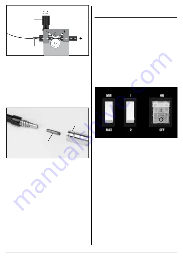
background image

– 8 –

FIG.

(11.1)

(11.2)

(11.3)

9.  Press the feed trigger on gun and observe the wire 

feed mechanism. If the wire is being fed correctly it 

will come out of the swan neck. If it jams you will 

need to remove the gas shroud 

(2.1)

 and with a 

small spanner unscrew and remove the tip 

(2.2)

Pass the tip over the wire and secure back onto the 

swan neck. Do not over tighten. Resecure the gas 

shroud and trim the wire back as required.

Note: Ensure the tip size matches the wire size prior to 

installing.

FIG.

(2.2)

(2.1)

7.4  NO GAS WELDING PRINCIPLE

For a successful weld joint, the molten metal must be 

protected from contaminating gases found in the air. 

This is achieved by using a flux cored filler wire. The flux 

is produced as the wire melts.
The flux creates a coating over the weld and once 

cooled will need to be removed by chipping it off.
If allowed to cool naturally some areas of the flux may 

ping off of the weld by themselves due to thermal 

contraction for this reason it is recommended that eye 

protection is worn.

8.  BASIC WELDING  


 OPERATION

NOTE: Although this machine is medium weight and 

portable take care. Do not manoeuvre over people’s 

heads.
Note: Welding is a mix of science and art and due to the 

complex principles and vast differences in parameters 

(ie. Material type, position, condition etc.) That 

information is well beyond the scope of this manual.

Draper Tools suggest training be obtained from a third 

party or refer to a suitable reference book on the subject 

additionally; nothing can beat practice using the welder 

on scrap material to get a better understanding.

8.1  ON/OFF SWITCH - FIG. 4

The on/off switch is a rocker switch. Press the top half in 

to switch the welder ‘on’ and the bottom half in to switch 

the welder ‘off’.

FIG.

8.2  WELDING CURRENT REGULATION 

SWITCHES

The current regulation switches regulate the welders 

power in four steps: 

Min +1, Min +2 and Max +1, Max +2. 

Regulate the welding current in conjunction with the wire 

speed to achieve the optimum arc for the workpiece 

thickness and type.

8.3  WIRE SPEED ADJUSTMENT 

– FIG. 5

Wire speed is dependent on material thickness and 

welding current. Being able to judge the correct wire 

speed based on the sound and quality of the weld will 

only come from practice.
• 

Too fast will result in holes blowing in the weld or the 

wire hitting the metal will force the torch backward.

• 

Too slow will result in the wire burning back to the 

torch into a ball and clogging the tip.

Note: When using the welder on a low amp setting/low 

wire speed, it is necessary that the wire drive tension is 

increased on the adjustment to avoid the spool stalling.

Содержание 63669

Страница 1: ...s been designed and contains all the necessary information to ensure its correct and safe use By following all the general safety instructions contained in this manual it will ensure both product and operator safety together with longer life of the product itself All photographs and drawings in this manual are supplied by Draper Tools to help illustrate the operation of the product Whilst every ef...

Страница 2: ...aution Information that draws attention to the risk of damage to the product or surroundings 1 3 EXPLANATION OF SYMBOLS Warning Read the instruction manual Warning Wear suitable welding eye face protection Warning Wear ear defenders During grinding operations Warning Wear protective gloves Keep out of the reach of children Warning Danger of electric shock Danger of fire Danger of explosion Danger ...

Страница 3: ...ructions before attempting to operate this product and save these instructions Electric shock can kill Remove the plug from the socket before carrying out adjustment servicing or maintenance Allow 5 minutes waiting time for the capacitors to discharge before removing the panels for any maintenance operations Do not touch live electrical parts Never use electrode holders or cables with damaged or d...

Страница 4: ...ion may be necessary against reflected radiation Wear safety glasses when chipping wire brushing grinding or when near cooling welds as metal filings or slag can be thrown up Fully enclosed goggles are advisable Arc machines generate a magnetic field which is detrimental to pacemaker recipients Consult your doctor before going near welding equipment operations The UV and IR radiation generated by ...

Страница 5: ...assageways on ladders or stairways and should be operated in accordance with the manufacturer s instructions In the vicinity of an arc non reflective curtains or screens shall be used to isolate persons from the arc radiation A warning e g a symbol for eye protection should refer to the hazard of arc radiation 4 UNPACKING AND CHECKING 4 1 PACKAGING Carefully remove the product from the packaging a...

Страница 6: ...er switch 7 On off switch 8 Thermal overload indicator 9 Power cable 10 MIG Spool hub 11 MIG wire feed assembly 12 Open catch 13 Flux cored wire 14 Face mask 15 Hammer brush FIG A 14 15 1 2 3 4 6 7 8 9 2 5 4 10 11 12 Note For details of our full range of accessories and consumables please visit drapertools com 13 Stock No 70050 shown ...

Страница 7: ... clear Equally ensure no debris can be drawn into the machine Make certain the location does not pose any hazards as detailed in the safety instructions before attempting to start the machine Note Refer to the rating label for energy input details Warning Remove the plug from the socket before carrying out adjustment servicing or maintenance 7 3 INSTALLING THE FILLER WIRE FIGS 1 3 The welding mach...

Страница 8: ...he complex principles and vast differences in parameters ie Material type position condition etc That information is well beyond the scope of this manual Draper Tools suggest training be obtained from a third party or refer to a suitable reference book on the subject additionally nothing can beat practice using the welder on scrap material to get a better understanding 8 1 ON OFF SWITCH FIG 4 The ...

Страница 9: ...itical to the arc and end results 6 FIG 7 FIG The position of the welding torch is important to achieve a good quality bead Position the torch at approximately 35 vertically and 75 horizontally and up to 20mm distance from the join 20mm is the maximum that can be achieved on the maximum setting Ensure the gas shroud remains clean of spatter Likewise and more importantly the wire feed tip must be k...

Страница 10: ... and vacuum the ventilation slots regularly Do not use solvents or fuels to clean the product When not in use store the product in a safe dry place 10 9 TROUBLESHOOTING 9 1 TROUBLESHOOTING WARNING For your own safety turn the switch off and remove the plug from the power supply socket PROBLEM POSSIBLE CAUSE REQUIRED ACTION Wire not feeding despite wire feed pulley turning Dirty current nozzle cont...

Страница 11: ...by misuse careless or unsafe handling alterations accidents or repairs attempted or made by any personnel other than the authorised Draper warranty repair agent Note If the tool is found not to be within the terms of warranty repairs and carriage charges will be quoted and made accordingly This warranty applies in lieu of any other warranty expressed or implied and variations of its terms are not ...

Отзывы: