28
Dräger PEX 1000
Operation
3.2
Switch on supply voltage
After having switched on the PEX 1000, all 14 LED segments including both decimal points
are activated for approx. 5 seconds ("lamp test") to make sure that they are not faulty.
During this period internal test routines start running in the PEX 1000, the output signal of
the PEX 1000 is 1 mA.
Then, the display shows two horizontal lines and the currently measured gas concentration
alternately, changing with approx. 1 Hz. During this period the output signal of the
PEX 1000 is 3.4 mA.
After one minute the PEX 1000 is ready for operation.
If the zero point does not fall below more than 1.25 %LEL or 0.25 %LEL, it shows the
currently measured value and the output signal equals the measured value.
3.3
During operation
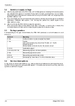
Corresponding to the gas concentration the PEX 1000 produces a current between 4 and
20 mA, or
3.4
Service interruptions
In the event of service interruptions, e.g. when performing maintenance and inspection work,
the PEX 1000 is ready for use again after approx. 10 minutes (sensor warm-up time) when the
system is switched on again.
Current
Meaning
0 mA
Cable is broken or power supply has failed
1 mA
Failure:
Zero point underrun by more than 5 %LEL or 1 %LEL
Electronic fault
Broken cable or short-circuit in the sensor circuit
3.4 mA
Calibration signal
3.8 mA to 20.5 mA
Measuring signal in normal operation
4 mA
Measuring signal zero point
20 mA
Measuring signal full-scale value
20.5 mA
Exceeded by more than 3 % of the full-scale value

