


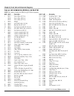
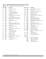


20
D R
®
HORIZONTAL/VERTICAL LOG SPLITTER
Splitting Wood
The control handle has three positions:
FORWARD
— Move the control handle forward to the FORWARD position to
move wedge toward the log to split (
Figure 42
).
Note:
The control handle will return to the NEUTRAL position as soon as the handle
is released (from the FORWARD position only).
NEUTRAL
— Release the control handle or move the lever to the NEUTRAL
position to stop the wedge movement (
Figure 43
).
REVERSE
— Move the control handle back to the REVERSE position to return the
wedge toward the cylinder (
Figure 44
). The control handle returns to the
NEUTRAL position automatically when fully retracted.
Do not hold the handle in the REVERSE position when fully retracted.
Note:
To stop the wedge before it is fully retracted when in the REVERSE position, the
handle must MANUALLY be put in the NEUTRAL position.
1.
Start the engine as instructed in the “Starting the Engine” section in this
chapter.
2.
Place the log on the Log Splitter. Grasp the log on the sides near the middle of
the log (
Figure 45
). Center the log, side-to-side, on the beam, making sure that
one end is against the end plate.
3.
Using only your hand, push the Control Lever Forward. If the log moves before
it is contacted by the Wedge, release the Handle and reposition the log.
4.
Hold the Control Lever, moving the Wedge towards the Log until the log is
split or the cylinder rod stops at its maximum travel position. Stop the Log
Splitter (forward movement), at any point in the splitting process, if you feel
an unsafe splitting condition is occurring. As the log is being split, DO NOT
reach forward and attempt to catch the split wood — let it fall.
5.
Once the Wedge reaches its full forward travel, move the Control Lever to the
Reverse Position and the Wedge will return to the retracted position.
Never operate the Log Splitter unless the hydraulic fluid tank is at the proper
level.
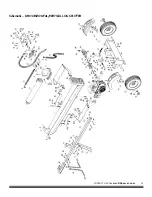
Figure 44
Control
Handle
Figure 43
Control
Handle
Figure 42
Control
Handle
If the control handle on your log splitter is not functioning properly, STOP
USE IMMEDIATELY and contact an authorized service dealer.
Do not attempt to service, repair or replace control valve. Contact an
authorized service dealer.
Do not attempt to adjust or modify the control valve or the hydraulic
system from its original settings or manufacturer in any way.
Hands on
Sides of
Log
Figure 45
End Plate