7
2.3.2 KDA Connection
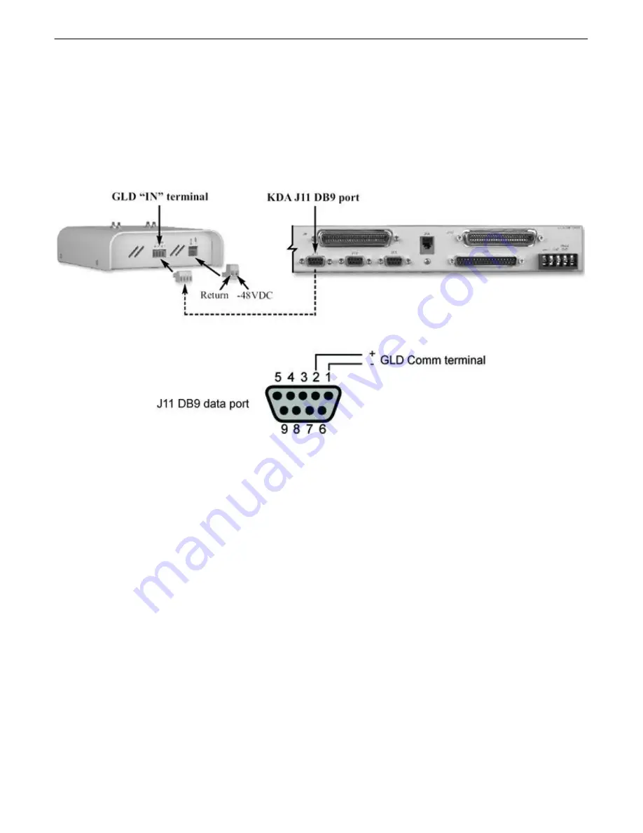
1). Connect communication wires from the J11 DB9 female connector on the back panel of the KDA. (See figure
2.3.2a)
2). From the J11 data port on the KDA, connect the communication wires to the 4 position barrier plug of the GLD.
Pin 1 is connected to the negative terminal of the GLD and pin 2 is connected to the positive terminal of the GLD.
(See figure 2.3.2b and table A)
Note: KDA Time Stamp version 1.7D and above is required to connect the GLD.
Fig. 2.3.2a - Communication lines between the KDA and GLD
Fig. 2.3.2b - KDA J11 pinout to GLD
Table A - J11 pinout information to GLD
J11 Pin # GLD Comm terminal Wire Color
1 Negative (-) Blue/White
2 Positive (+) White/Blue


