USER MANUAL
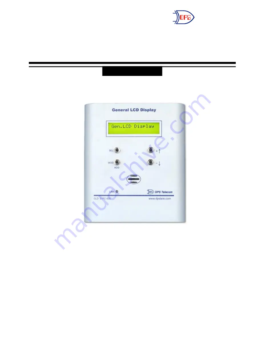
General LCD Display (GLD)
June 2, 2010
Visit our website at www.dpstelecom.com for the latest PDF manual and FAQs.
D-OC-UM106.02100
DPS Telecom
“Your Partners in Network Alarm Monitoring”
Version 1.0F
Страница 1: ...R MANUAL General LCD Display GLD June 2 2010 Visit our website at www dpstelecom com for the latest PDF manual and FAQs D OC UM106 02100 DPS Telecom Your Partners in Network Alarm Monitoring Version 1...
Страница 2: ...her mechanical electronic or any other means in whole or in part without prior written consent from DPS Telecom except as required by United States copyright laws The material in this manual is for in...
Страница 3: ...1 0E or newer 2 2 2 5 2 2 2 1 Setting Baud Rate 5 LED Indications 2 2 3 5 Audible Notification 2 2 4 5 LCD Operation 2 2 5 5 Host Connections 2 3 6 Multiple GLDs 2 3 1 6 KDA Connection 2 3 2 7 2 3 2 1...
Страница 4: ......
Страница 5: ...that up to 3 GLDs can be connected to a single host with a maximum range of 1 500 feet between the host and the last GLD unit the 1 500 foot maximum applies to a single GLD as well The GLD is also eas...
Страница 6: ...2 1 2 1 Shipping List...
Страница 7: ...wer Input 48VDC Current draw 100mA Fuse Internal Interface RS485 Operating Temperature Range 0 to 60 degrees Celsius 32 to 140 degrees Fahrenheit Operating Humidity Range 0 to 95 non condensing Mounti...
Страница 8: ...position barrier plug 5 All barrier screws should be seated firmly but not over tightened so as to nick the bare wire 6 Push the plugs firmly back into their appropriate location on the bottom of the...
Страница 9: ...baud rate mode by simultaneously holding down the and buttons 2 Press you will see GLD baud 3 Press SEL then use the buttons to adjust baud rate 3 Press SEL to set 4 Press MOD to exit 2 2 3 LED Indic...
Страница 10: ...Up to twelve GLDs can be installed at one site The units can be connected to a host in a daisy chain configuration as shown in the figure below or in a star configuration Whether connecting 1 2 or 12...
Страница 11: ...f the GLD Pin 1 is connected to the negative terminal of the GLD and pin 2 is connected to the positive terminal of the GLD See figure 2 3 2b and table A Note KDA Time Stamp version 1 7D and above is...
Страница 12: ...connecting 1 3 in the auxiliary displays section and press OK See figure 2 3 2 1b Note The Firmware type must be set to Timestamp and Docking module 1 must be set to RS485 See figure 2 3 2 1b Fig 2 3...
Страница 13: ...bove is required to connect the GLD The NetGuardian must have an RS485 or RS232 port for GLD support Communication lines between the NetGuardian G2 and GLD Communication lines between the NetGuardian...
Страница 14: ...l down to the Options portion of the Ports screen 3 Enter the number of GLDs you are connecting to the NetGuardian 4 Hit the Submit Data button Note If connecting more than 3 GLDs set the NetGuardian...
Страница 15: ...n to the Options portion of the Ports screen 3 Enter the number of GLDs you are connecting to the NetGuardian G4 4 Hit the Submit Data button Note If connecting more than 3 GLDs set the NetGuardian G4...
Страница 16: ...n to the Options portion of the Ports screen 3 Enter the number of GLDs you are connecting to the NetGuardian G5 4 Hit the Submit Data button Note If connecting more than 3 GLDs set the NetGuardian G5...
Страница 17: ...positive terminal of the GLD and tie communication wires 1 and 3 together for connection to the negative terminal of the GLD 4 For software configuration for the IAM see the section in this manual reg...
Страница 18: ...ble D 3 Tie communication wires 1 and 6 together for connection to the positive terminal of the GLD and tie communication wires 2 and 5 together for connection to the negative terminal of the GLD Note...
Страница 19: ...ion See figure 2 3 7 1b 5 Setup port usage for DCP F Interrogator 2400 BAUD See figure 2 3 7 1b 6 Select Enter Enter sets the automatic defaults until you reach the DCPF Mode setting and type X See fi...
Страница 20: ...e 2 3 7 1c Fig 2 3 7 1c Enter the default settings in the Remote Device screen except for the fields highlighted above Model Numbers General LCD Display GLD D PC 820 10A 04 DB9 cable NetGuardian D PR...
Страница 21: ......
Страница 22: ......
Страница 23: ...oses other than those for which it was designed d damage caused by disasters such as fire flood wind or lightning unless and to the extent that the product specification provides for resistance to a d...
Страница 24: ...eets Exclusive user forms Expert tips on using your alarm monitoring equipment advanced techniques that will save you hours of work Educational White Papers deliver fast informal tutorials on SNMP ASC...