background image

10.4.3 - “Remote” memorisation

You can store a new radio transmitter in the control unit, without pressing 

its keys directly. A previously memorised and operational “OLD” trans-

mitter must be available. The “NEW” radio transmitter to be stored will 

“inherit” the characteristics of the OLD one; that is, if the OLD radio trans-

mitter is memorised in mode 1, the NEW will be memorised in mode 1; 

in this case, during the programming phase, any key can be pressed 

on either of the two transmitters. If, on the other hand, the OLD radio 

transmitter is memorised in Mode 2, you must press the key with the 

command you want on the OLD transmitter, and on the NEW, the key to 

which you want to associate that command.
Holding the two transmitters, position yourself within the operating range 

of the automation and perform the following operations:

01.

  Press the key on the NEW radio transmitter and hold it down for at 

least 5s, then release it.

02.

  Press the button on the OLD radio transmitter 3 times slowly.

03.

  Press the key on the NEW radio transmitter once slowly.

At this point, the NEW radio transmitter will be recognised by the control 

unit, and take on the characteristics that the OLD one had.
If there are other transmitters to memorise, repeat all the above steps for 

each new transmitter.

10.4.4 - Deleting a radio transmitter

If you have available only one radio transmitter, use this operation to 

delete it.

If the transmitter is memorised in Mode 1, one deletion phase is sufficient 

and at point 3 you may press any key. If the transmitter is stored in mode 

2, a deletion phase is required for each memorised key.
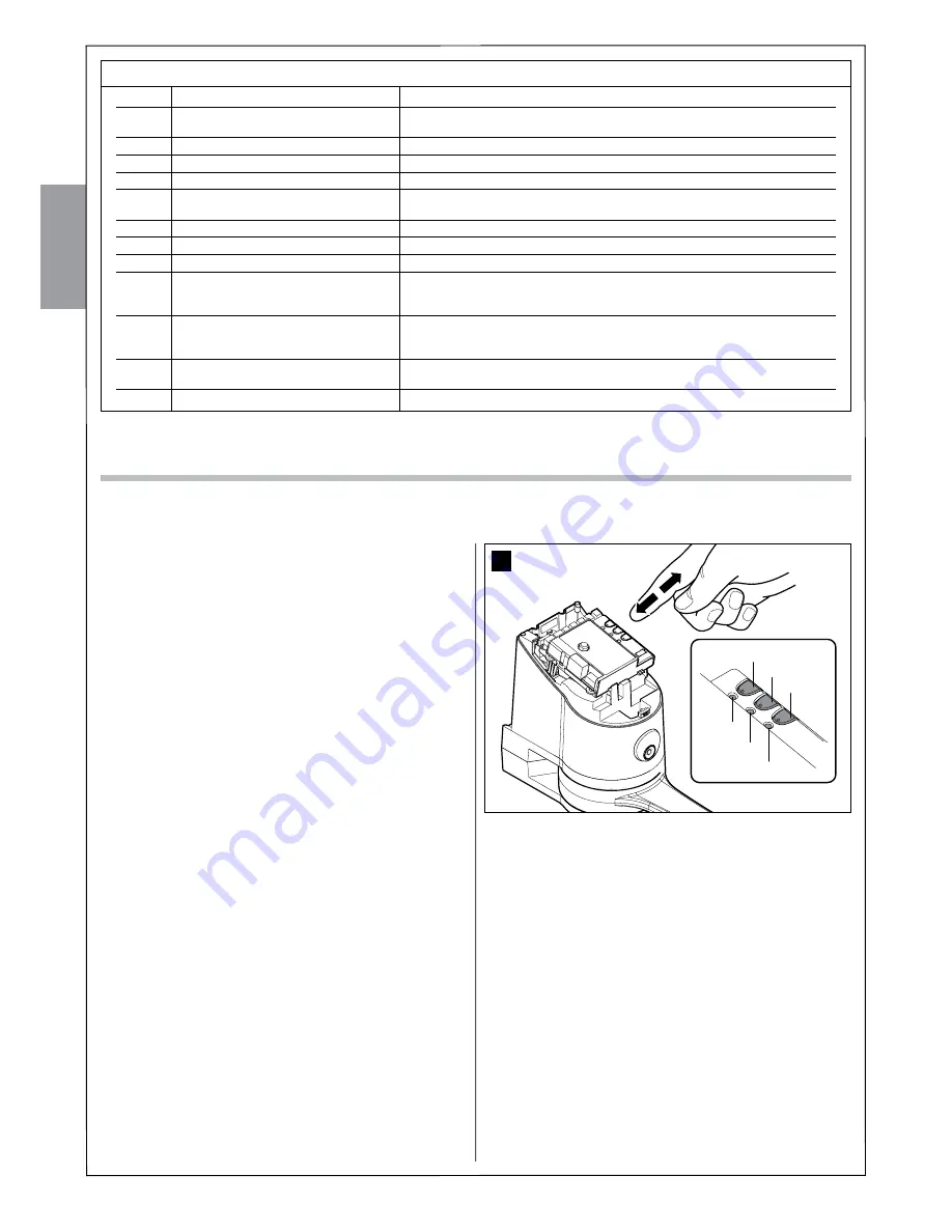
01.

  Press the P1 key 

[B]

 key (

fig. 38

) on the control unit and hold it 

down.

02.

  Wait until the LED P1 lights up, within three seconds.

03.

  Press the key of the radio transmitter to be deleted for at least three 

seconds. If cancellation was successful the LED P1 will flash quick-

ly five times. If LED P1 emits 1 slow flash, the deletion phase was 

unsuccessful because the transmitter is not memorised.

04.

  If there are other transmitters to delete, keeping P1 depressed, 

repeat step 3 within another 10 seconds; otherwise, the deletion 

phase will stop automatically.

English

20

 – English

10.4.5 - Deleting all memorised radio transmitters

This operation deletes all memorised transmitters.

01.

  Press the P1 key 

[B]

 key (

fig. 38

) on the control unit and hold it 

down.

02.

  Wait for the P1 LED to light up, then wait for it to switch off and then 

wait for it to flash 3 times.

3

 Release button P1 exactly during the third flash.

4

 Wait for around 4s for the deletion phase to finish; during this time the 

LED P1 will flash very quickly.

If the procedure is successful, after a few moments the P1 LED will flash 

slowly 5 times.

TABLE 9

1 time 

“Open” command 

Commands the automation as described in table 3 (Open function)

2 times 

“Pedestrian opening” command 

Causes partial opening of one or two leaves as described in table 3  


(Pedestrian Opening)

3 times 

“Open only” command 

Causes the leaves to open (open - stop - open etc.)

4 times 

“Close only” command 

Causes the leaves to close (close - stop - close etc.)

5 times 

“Stop” command 

Halts the manoeuvre

6 times 

“Apartment block open” command 

The command has no effect on opening, when closing the command causes   


the movement to reverse, that is, opens the leaves

7 times 

“High priority open” command 

Works also when the automation is locked

8 times 

“Pedestrian opening 2” command 

Causes partial opening of leaf M2, equal to halfway

9 times 

“Pedestrian opening 3” command 

Causes partial opening of both the leaves, equal to halfway

10 times 

“Open + lock automation” command 

Causes an opening manoeuvre and when this is complete, the automation is locked;  


the control unit will not accept any command other than “High priority open” and  


“Release” of the automation

11 times 

“Close + lock automation” command 

Causes a closure manoeuvre and when this is complete, the automation is locked;  


the control unit will not accept any command other than “High priority open” and  


“Release” of the automation

12 times 

“Lock automation” command 

Causes a halt of the manoeuvre and locks the automation; the control unit will not  


accept any command other than “High priority open” and “Release” of the automation.

13 times 

“Release automation” command 

Causes automation release and reset to normal operation

P1

LP1

LP2

LP3

P2

P3

38

LED P1

LED P2

LED P3

Содержание WS200S

Страница 1: ...Instructions and Warnings for Installation and Use WS200S...

Страница 2: ...L100 FLASHING INDICATOR 10 PROGRAMMING STEP 7 12 7 1 POWER SUPPLY CONNECTION 12 7 2 PRELIMINARY CHECKS 12 7 3 CONNECTED DEVICES RECOGNITION 12 7 4 GATE LEAF OPEN AND CLOSURE ANGLES RECOGNITION 12 7 5...

Страница 3: ...ct must be performed exclusively by a qualified and skilled technician However all preliminary set up installation connection of devices to one another and programming operations may be performed by p...

Страница 4: ...h both the data in this paragraph and the technical data in the chapter Product technical speci fications 1 Check that the gate leaf has dimensions and weight which fall within the following limits ma...

Страница 5: ...unt that due to possible deposits of water in the routing ducts the ducting might create con densation in the control unit with consequent damage to the electronic circuits Place the ends of the ducti...

Страница 6: ...C D D E F a d g d e f b b c 1 3 5 English English 5 A B F 2 G D F C 110 120 130 140 150 160 170 180 190 200 210 220 230 240 250 260 270 280 290 300 0 20 40 60 80 100 120 140 160 180 200 220 240 90 95...

Страница 7: ...using just a slight movement move the gate leaf a few centimetres in the direction of full opening until you hear a click 14 If the gate to be automated is a dual leaf type repeat the same operations...

Страница 8: ...English 7 English E B A 6 Distance E minimum 400 mm 8 9 M8 V6 x 70 M6 10 11 12 13 7...

Страница 9: ...8 English OK b c d a Maximum 14 14 15 16 17 18 19 21 20 M8 M8 M8 M8...

Страница 10: ...English 9 English OPEN STOP TX RX HS100 PH100 FL100 WK100SK M1 WS100SCK ECS bus ECS FLASH bus M M M M Blue Yellow Green Brown B A 22 23 WS100SCK M2 WS100SK M1 24 Brown Yellow Green Blue...

Страница 11: ...ig 25 4 From an electrical point of view TX and RX are connected in parallel to one another fig 25 5 and to the blue terminal on the control card You do not need to observe any polarity 07 Affix the h...

Страница 12: ...English English 11 26 A B 6 mm x4 6 mm x4 A B A B A B A A A A B B B 1 2 3 4 4 A B A B A B A B A B A B 5 6 7 8 9 11 12 10 A B A B...

Страница 13: ...e P2 LED flashes it means that an error has occurred see section 10 5 Troubleshooting The phase of self learning the devices connected can be repeated at any time also after installation such as in th...

Страница 14: ...ed according to the risks present and for ensuring observance of all legal provisions standards and regulations and in particular all requirements of the standard EN 12445 which establishes the test m...

Страница 15: ...ter to change T1 T2 STEP 9 The maintenance operations must be performed in strict com pliance with the safety directions provided in this manual and according to the applicable legislation and standar...

Страница 16: ...imes Motor 1 and Motor 2 discharge in closure 1 No discharge Press T3 once 2 0 1s Minimum Press T3 twice 3 0 2s Press T3 three times 4 0 3s Press T3 four times 5 0 4s Medium Press T3 five times 6 0 5s...

Страница 17: ...ch which allows you after having correctly entered the secret combination to control the automation remotely For programming see paragraph 10 4 6 10 2 1 Installing the PR3 buffer battery fig 33 CAUTIO...

Страница 18: ...e Ea 14 Am 200 thus Ed 2800 Establish the energy consumed To calculate the energy consumed by the automation proceed as follows 05 In the table below choose the box corresponding to the intersection o...

Страница 19: ...during the self learning phase after which a STOP command is activated whenever a variation with respect to the learned status is detected 10 3 3 Recognition of Other Devices Normally the recognition...

Страница 20: ...llowing paragraphs before you proceed with their execution 10 4 1 Mode 1 memorisation 01 Press P1 fig 35 for at least 3 s When the LED P1 lights up release the key 02 Within 10s press any key on the r...

Страница 21: ...pressed repeat step 3 within another 10 seconds otherwise the deletion phase will stop automatically English 20 English 10 4 5 Deleting all memorised radio transmitters This operation deletes all memo...

Страница 22: ...inter mittent the voltage value is not important approximately 10 30 Vac if there is voltage the problem is due to the lamp in this case replace the lamp with one having the same characteristics TABLE...

Страница 23: ...egular operation and when there is a problem see Table 13 Quick flashes 1 flash 1 second pause 1 flash 2 flashes 1 second pause 2 flashes 3 flashes 1 second pause 3 flashes 4 flashes 1 second pause 4...

Страница 24: ...ognition phase in progress Action Cycle operation Complete cycle operation Carry out the recognition phase see chapter 3 5 2 Leaf open and closure angles recognition Indicates that the open angles sel...

Страница 25: ...bly shorter than 5m observe the warnings regarding minimum gauge and type of cables Ambient operating temperature 20 50 C Use in acid saline or potentially explosive atmospheres NO Mounting On a horiz...

Страница 26: ...th Addressing capability Ambient operating temperature Use in acid saline or potentially explosive atmospheres Mounting Protection rating Dimensions weight Presence detector for automation of automati...

Страница 27: ...utomatic gates and doors AM OOK radio encoded modulation 433 92 MHz Rolling code with 64 Bit code 18 billion billion combinations 4 each key can be used for the various control unit commands or to com...

Страница 28: ...PH100 and FL100 conform to DIRECTIVE 2004 108 EC OF THE EUROPEAN PARLIAMENT AND COUNCIL of December 15 2004 concerning alignment of Member States legislation regarding electromagnetic compat ibility...

Страница 29: ...ready ready for use and the four keys have the following functions fig 42 This table must be compiled by the person who programmed the automation Function T1 Key T2 Key T3 Key T4 Key Action Rotated to...

Страница 30: ...ing leaves and stones to ensure that noone can operate the door Check the system periodically in particular all cables springs and supports to detect possible imbalance signs of wear or damage Do not...

Страница 31: ......

Отзывы: