


WIL-10470-E-05
12
PS1 Clamped Metal
NOTE:
In the event of a power failure, close the shut-
off valve if you do not want the pump to restart when the
power returns.
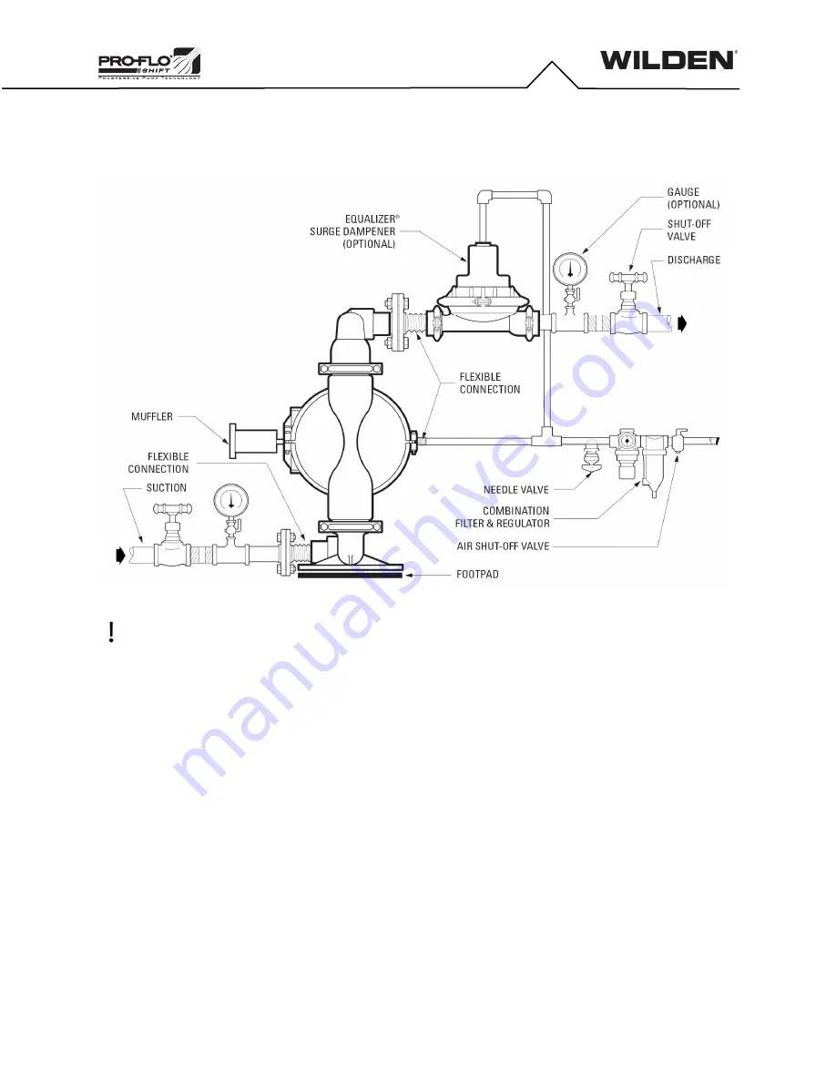
Air-Operated Pumps:
To stop the pump from operating in an
emergency, simply close the shut-off valve (user-supplied) installed in
the air supply line. A properly functioning valve will stop the air supply
to the pump, therefore stopping output. This shut-off valve should be
located far enough away from the pumping equipment such that it can
be reached safely in an emergency.
Operation
The Pro-Flo SHIFT pumps are pre-lubricated and do not require in-
line lubrication. Additional lubrication will not damage the pump.
However, if the pump is heavily lubricated by an external source, the
pump’s internal lubrication maybe washed away. If the pump is then
moved to a nonlubricated location, it may need to be disassembled
and re-lubricated as described in “Disassembly/ Reassembly”.
Pump discharge rate can be controlled by limiting the volume and/or
pressure of the air supply to the pump. An air regulator is used to
regulate air pressure. A needle valve is used to regulate volume.
Pump discharge rate also can be controlled by throttling the pump
discharge by partially closing a valve in the discharge line of the
pump. This action increases friction loss, which reduces flow rate.
(See “Performance”) This is useful when the need exists
to control the pump from a remote location. When the pump
discharge pressure equals or exceeds the air supply pressure, the
pump will stop. No bypass or pressure relief valve is needed, and
pump damage will not occur. The pump has reached a “deadhead”
situation and can be restarted by reducing the fluid discharge
pressure or increasing the air inlet pressure. Wilden Pro-Flo SHIFT
pumps run solely on compressed air and do not generate heat.
Therefore, your process fluid temperature will not be affected.
Maintenance and Inspections
Because each application is unique, maintenance schedules maybe
different for every pump. Frequency of use, line pressure, viscosity
and abrasiveness of process fluid all affect the parts life of a Wilden
pump. Periodic inspections have been found to offer the best means
for preventing unscheduled pump downtime. Personnel familiar with
the pump’s construction and service should be informed of any
abnormalities that are detected during operation.
SUGGESTED INSTALLATION, OPERATION, MAINTENANCE
AND TROUBLESHOOTING
Содержание PSG WILDEN Pro-Flo SHIFT PS1
Страница 27: ...WIL 10470 E 05 27 PS1 Clamped Metal NOTES ...


